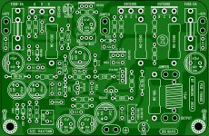
nice curvy layout!. small correction on silk, c2 220p.It seems a bit quiet here,so let get to more quasi.I`ve got a surprise and i think you will like it.The layout was promised last week and i`ve been trying to upload since last week Tuesday on my cellphone.Definitely a nightmare.
Without further ado,let`s get cracking.
First a thanks to everyone for the positve feedback.I`ve made a couple of changes which i think is for the better.
Let`s not drag this out and let the layout speak.
Regards
phunk
ps:There are gerbers,pdf`s and a Sprint lay file of each version in the zip files.
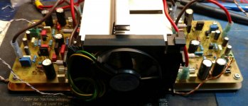
pic 3 looks very like the hand drawn traces one found in 1970s manufacture, before CAD was allowed to take over our thinking. Very retro and nice.It seems a bit quiet here,so let get to more quasi.I`ve got a surprise and i think you will like it.The layout was promised last week and i`ve been trying to upload since last week Tuesday on my cellphone.Definitely a nightmare.
Without further ado,let`s get cracking.
First a thanks to everyone for the positve feedback.I`ve made a couple of changes which i think is for the better.
Let`s not drag this out and let the layout speak.
Regards
phunk
ps:There are gerbers,pdf`s and a Sprint lay file of each version in the zip files.
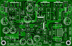
Silkscreen corrections
Thanks for the extra eyes and compliments guys.I think i should change the default colour scheme in Sprint.The colours seems to merge in my brain after a while.
Corrections have been made to the silkscreeen,gerbers and lay file.
Regards
phunk
Thanks for the extra eyes and compliments guys.I think i should change the default colour scheme in Sprint.The colours seems to merge in my brain after a while.
Corrections have been made to the silkscreeen,gerbers and lay file.
Regards
phunk
Attachments
BIG QUASI
Thiago, Congrats!, thats a very nice layout!. As Bangla says, it should rumble some windows and houses..
reg
Prasi
I don't like, I love  Congrats
If you do more minor change, you could change the +/-42V on the silkscreen for +/- 50V just to match the schematic.
This week-end, I'm ordering the pieces for the regular Quasi.
BR,
Eric
Congrats If you do more minor change, you could change the +/-42V on the silkscreen for +/- 50V just to match the schematic.
This week-end, I'm ordering the pieces for the regular Quasi.
BR,
Eric
Hi All
I haven't built anything for several years but I'm keen to start a new project. I've been following this thread and fancy etching my first boards. I'll start this tomorrow. I can make the under mounted fets work with my heatsinks, but it may be easier if they were located at the side of the board. Has someone designed a board that I may have missed? No worries if not 🙂
Many thanks
Richard
Hi All
I haven't built anything for several years but I'm keen to start a new project. I've been following this thread and fancy etching my first boards. I'll start this tomorrow. I can make the under mounted fets work with my heatsinks, but it may be easier if they were located at the side of the board. Has someone designed a board that I may have missed? No worries if not 🙂
Many thanks
Richard
Thiagomogi's layout above is for vertical mounted heatsink.
Christmas not boring - Qusi solder Fest
best time to order so you have to do and not only food and looking movies
and being lazy in Christmas Periode. 😀 😀 🙄
Eric,I'm ordering the pieces for the regular Quasi.
best time to order so you have to do and not only food and looking movies
and being lazy in Christmas Periode. 😀 😀 🙄
This thread moves fast! new layouts and now a Big Quasi...
Tonight I listened for 2 hrs with headphones and it does sound good.
I loaded the output with 7R 15W resistors and ran the 50R phones off that.
the first one was built with whatever compensation caps I had, mostly MLCC and closest value.
the second board uses wilma MKP and so thought I might hear some difference.
Square wave response shows some spikes on the side I used the correct value cap's.
the output coils are not installed, are they needed for testing? or just for speaker duty?
my understanding is they protect the amp from the speakers.
anyway Great thread, and Thanks
Attachments
No, Max, not tested. However, I can guarantee 100% that it will work well without instability, BUT the big question is HOW good the SOUND is vis a vis the smaller Quasi......
Cheers,
Hugh
Cheers,
Hugh
- Home
- Amplifiers
- Solid State
- Very simple quasi complimentary MOSFET amplifier