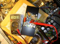
ready for testing
Hi Fellas.
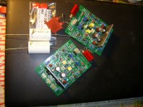
Now i have finitely finished the boards paralleled to other projects.😉
First i could say: it does not zeroes the Offset with two red LED- 1,8V- to much
voltage left over ~1,7V with fully cw turned 500 Ohm trimmer.
I soldered in only one greenLED and it works fine than.
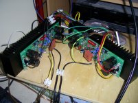
R5 is 100k; D7 is 3,3V; N-VFet is: FQA 19N20 Vgs ~4,6V; BJT is 2S3263 LATP Sanken.
Bias runs stable 39,4.....9mV and offset from 1....4mV.
Heat Sink is a Fischer SK53 75mm high- dissipate 0,75K/W.
Now its time to fix both channels for stereo listen test.
Hope it goes on with other builds to see here.
Cheers Bangla.
Hi Fellas.
Now i have finitely finished the boards paralleled to other projects.😉
First i could say: it does not zeroes the Offset with two red LED- 1,8V- to much
voltage left over ~1,7V with fully cw turned 500 Ohm trimmer.
I soldered in only one greenLED and it works fine than.
R5 is 100k; D7 is 3,3V; N-VFet is: FQA 19N20 Vgs ~4,6V; BJT is 2S3263 LATP Sanken.
Bias runs stable 39,4.....9mV and offset from 1....4mV.
Heat Sink is a Fischer SK53 75mm high- dissipate 0,75K/W.
Now its time to fix both channels for stereo listen test.
Hope it goes on with other builds to see here.
Cheers Bangla.
Attachments

hi bangla,Hi Fellas.
Now i have finitely finished the boards paralleled to other projects.😉
First i could say: it does not zeroes the Offset with two red LED- 1,8V- to much
voltage left over ~1,7V with fully cw turned 500 Ohm trimmer.
I soldered in only one greenLED and it works fine than.
R5 is 100k; D7 is 3,3V; N-VFet is: FQA 19N20 Vgs ~4,6V; BJT is 2S3263 LATP Sanken.
Bias runs stable 39,4.....9mV and offset from 1....4mV.
Heat Sink is a Fischer SK53 75mm high- dissipate 0,75K/W.
Now its time to fix both channels for stereo listen test.
Hope it goes on with other builds to see here.
Cheers Bangla.
thats as good an inductor as the best ones on the forum... German precision🙂. ...
reg
prasi
Is that a polyester cap at the input ? Some are good and some are not. You could check different types , as it's a crucial component. Polypropylene could be better but not all polyprops sound great ! Experiment with a few types if you can.
its a CBB film cap, the type (physical and color) that i have seen in many cheap led bulb ckts, very very cheap from china. still to get any meaningful article / write up for their use in audio signal path.Is that a polyester cap at the input ? Some are good and some are not. You could check different types , as it's a crucial component. Polypropylene could be better but not all polyprops sound great ! Experiment with a few types if you can.
I have Panasonics that are same shape and color as CBB. The CBB's I have seen to work well and sonic signature is good - especially the 250v or 400v rated ones.
Gerber files possible?
Hello Thiago, looks good, I like your layout better than the ones with outputs under the PCB. Would like to have a go at this amp. But can you please upload Gerber files of your layout also?..
Best Regards, Jonas
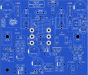
Here is PCB with final figures.
Tested and working.
Sprint attached file.
Regards
Thiago
Hello Thiago, looks good, I like your layout better than the ones with outputs under the PCB. Would like to have a go at this amp. But can you please upload Gerber files of your layout also?..
Best Regards, Jonas
it is an honor.
Gerbe attached.
Regards
Thiago
Gerbe attached.
Regards
Thiago
Attachments
Last edited:
Thank you very much 🙂
Edit: I wish you had kept the Thiele output network on the PCB though..
Edit: I wish you had kept the Thiele output network on the PCB though..
Last edited:
its a CBB film cap
CBB is a polypropylene cap. Can be easily confirmed by measuring the value at room temp and heated in very hot water ! The capacitance will drop for polypropylene. For polyester it will increase.
Last edited:
Hello everyone
I never used Sprint Layout to print typons but I was interested to make this amplifier and this is what I get with this. 😕
A configuration issue, an idea?
Thank you.
Are you using SLayout with PDFCreator? If yes, in my experience it sucks! 😱
Try the virtual pdf printer of Foxit Pro.
Regards.
Yes that's right!Are you using SLayout with PDFCreator? If yes, in my experience it sucks! 😱
Try the virtual pdf printer of Foxit Pro.
Regards.
I'll try the virtual pdf printer of Foxit.
Thank you.
Righto...
I have implemented the changes to the layout.
I have also made a couple of changes and have included the old layout in zip format as reference:-
1.D1,D2&R3 brought in line;
2.D5&D6 shifted to the front of the output mosfet contacts.Was a bit worried about the lead lenght of the outputs.Datasheet says +- 14,6mm.
3.Led1,Vr1,C3,R6,D9&D10 shifted around to get some clearance because of the 12mm dia caps instead of the 10mm dia caps that were previously there.Left C11&C13 where they were because the only space on top for C13 would have been very close to R21 which i did not like because of R21`s heat.
Let me know which options i should include in the final layout as i want to finalise & order pcb`s by the end of this month(surface mail takes+- 6 weeks,so will be good to go for the big days).
Thanks
phunk
Attachments
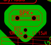
Forgot to mention the extra hole in the left hand corner.It`s for a strain relief clip for the input signal cable(cable tie for quick testing).
whats that green alien doing right at the output connector?.😀 see closely, two eyes and two holes for mouth and nose... niceRighto...
I have implemented the changes to the layout.
I have also made a couple of changes and have included the old layout in zip format as reference:-
1.D1,D2&R3 brought in line;
2.D5&D6 shifted to the front of the output mosfet contacts.Was a bit worried about the lead lenght of the outputs.Datasheet says +- 14,6mm.
3.Led1,Vr1,C3,R6,D9&D10 shifted around to get some clearance because of the 12mm dia caps instead of the 10mm dia caps that were previously there.Left C11&C13 where they were because the only space on top for C13 would have been very close to R21 which i did not like because of R21`s heat.
Let me know which options i should include in the final layout as i want to finalise & order pcb`s by the end of this month(surface mail takes+- 6 weeks,so will be good to go for the big days).
Thanks
phunk
I really haven't seen so many PCB layouts for the very same amp circuit recently!
This is awesome!
Yesterday I started soldering the low level components (resistors, diodes, jumpers).
This is awesome!
Yesterday I started soldering the low level components (resistors, diodes, jumpers).
I really haven't seen so many PCB layouts for the very same amp circuit recently!
This is awesome!
Yesterday I started soldering the low level components (resistors, diodes, jumpers).
That is the way I populate too. I start with the lowest profile parts and work my way up. That way the table helps hold the parts tight to the boards during soldering.
whats that green alien doing right at the output connector?.😀 see closely, two eyes and two holes for mouth and nose... nice
I had already noticed that on an earlier post! 😛
Much to do with this circuit!!!
Attachments
That is the way I populate too. I start with the lowest profile parts and work my way up. That way the table helps hold the parts tight to the boards during soldering.
I cannot ever catch the right words... lowest profile parts! Thank you! 😉
Quasi for Homecinema only in Stereo
Hi Fellas.
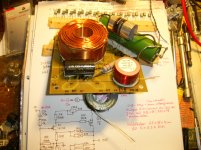
Thank you Prasi for kind words about inductor- it's only handcrafted over a 10mm drill. 😛
Here are some speculation about my used input cup.
It is a Nichicon QXP- other named it Relcap. On Greg's DX Amp side i noticed it
first time and was searching some information.
Reliable Capacitor (RelCap,AudioCap,Multicap)PPFA,PPFX,PPFXS,RT,RTX,TFT
So i bought some 1uF from Mouser and tested it in FetZilla with excellent results- if you keep in mind: size/price/performance relation. 😀 😀
Than i also make tests with MBGCH- really a Favorit too and with MBGO- that is the one i prefer for long time listening- smooth and relaxed, but feels lost a bitin clear transparency to QXP.
Finally i have add a little 10n K40Y-9 PIO to QXP- and if i trust my ears i can live long time with that.
On VSSA/Spooky boards i use a combi with DME cap with very good result.
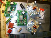
I send picture about my Favorit tested cap collection.
You can see on 2 way X over board a clarity ESA 4uF to a PIO 3,3uF/250V K75-10 hybrid cap, and believe or not- that is a awesome combi in use for
the tweeter in my unfinished project after long period testing.
Another Favorit in bypass is the Orange Drop P715/716- what i have tested
for decoupling in Tubeamp and on Circlophone.
One of my loved overall performance/price is the Audyn Plus- the white in picture, only 0,68uF/800V- a huge one.
I feel it is not thrown away money if you like to test yourself. 🙄
I am not so good in details to explain but i trust my lazy ears. 😎
Regards.
Hi Fellas.
Thank you Prasi for kind words about inductor- it's only handcrafted over a 10mm drill. 😛
Here are some speculation about my used input cup.
It is a Nichicon QXP- other named it Relcap. On Greg's DX Amp side i noticed it
first time and was searching some information.
Reliable Capacitor (RelCap,AudioCap,Multicap)PPFA,PPFX,PPFXS,RT,RTX,TFT
So i bought some 1uF from Mouser and tested it in FetZilla with excellent results- if you keep in mind: size/price/performance relation. 😀 😀
Than i also make tests with MBGCH- really a Favorit too and with MBGO- that is the one i prefer for long time listening- smooth and relaxed, but feels lost a bitin clear transparency to QXP.
Finally i have add a little 10n K40Y-9 PIO to QXP- and if i trust my ears i can live long time with that.
On VSSA/Spooky boards i use a combi with DME cap with very good result.
I send picture about my Favorit tested cap collection.
You can see on 2 way X over board a clarity ESA 4uF to a PIO 3,3uF/250V K75-10 hybrid cap, and believe or not- that is a awesome combi in use for
the tweeter in my unfinished project after long period testing.
Another Favorit in bypass is the Orange Drop P715/716- what i have tested
for decoupling in Tubeamp and on Circlophone.
One of my loved overall performance/price is the Audyn Plus- the white in picture, only 0,68uF/800V- a huge one.
I feel it is not thrown away money if you like to test yourself. 🙄
I am not so good in details to explain but i trust my lazy ears. 😎
Regards.
Attachments
Bangla,
I noticed your FetZilla in your photos - how do you find it sonically?
I will be very interested to hear your view comparing the FetZ will the Quasi. Very different designs, but a few of the same design tricks.....
Phunk,
You have done a very nice pcb for the Quasi, with all electros orientated the same way and the output devices dead center to the amp can be located centrally on a small heatsink. Elegant! How many different designs do we have for this amp now? Three, or four? Perhaps it's a pretty good circuit! Notice that the good circuits are simple, low parts count, and well reviewed sonically. No one notices too much if the THD is high.....
Hugh
Last edited:
- Home
- Amplifiers
- Solid State
- Very simple quasi complimentary MOSFET amplifier