...
The safety aspect is just that the sleeve serves as a warning for high voltages? I can't see any other purpose as the wire itself is rated for high temp/abrasion etc.
...
No - it's safety. Don't know exactly if this is needed generally inside the amplifier but especially the thin wires through a hole in your iron plate should be double isolated. IMHO if they cross low voltage cables there is double isolation needed.
DC below 75V is low voltage as defined in EU paper 2014/35/EU.
BR, Toni
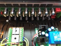
Left sided is the fan controller - is controlling the 3 fans.PS: what is the box on the left of the chassis in that pic? And the star ground is on the output relay/zobel board?
And yes - double star ground is integrated on the output relay/zobel board.
BR, Toni
Ok I understood double insulation was only a requirement for products which don't have a connection to safety earth. That's not to say it isn't sensible practice however. For me to sleeve the toroid primaries I would need to dismantle everything (right down to the feet). After today's mammoth effort that isn't going to happen. I will look at the 0.62mm^2 runs - I have done the MCU wiring already because it is readily accessible. Thx.
BTW I'm thinking the short runs from the input board to IPS/VAS should really be coax. Thoughts?
RSAVAS, that pioneer SX 1050 would've been great for this.
The Sx780 I have now puts out 75 wpc 8 ohms with IRF240 , 9240 fets in it.
circuit same except it lacks constant current source for matched differential pair
I also had to boost the regulators from 40v to 44v
The last test is of a 6922 tube used in place of TA7136p which now drives the volume pot with a gain of 8.
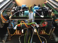
Last few stages. Routing Sig-Out from OPS to output relay boards. Hopefully the iron shelf offers some shielding.
Looks good! I'm sure, the iron shelf will help a lot! If possible route the speaker out signal with a bit more distance to the iron shelf edges.
BR, Toni
Last edited:
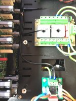
Upper deck IPS/VAS installed. 230V runs to Aux PSUs and MCU shielded with braid. Third NTC heat monitor installed between IPS/VAS. Just need to solder connections to speaker terminals.
Perfect! Third NTC is correctly placed here. If someone blocks the chassis upper vents, the amplifier will auto power off, if heat exceeds 50 - 60 degree inside!
BR, Toni
Bench testing finished under Toni's good guidance. (No performance measurements made.) While I still have a couple of tidy up things to do, the time has come to connect speakers. I'm almost too scared to. What of my first amp build, after months of work, doesn't work properly? 😱
Attachments
Last edited:


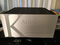
A "quick speaker test" has turned into about 3 1/2 hours of constant use so far. Initial impressions: the sound is very good. I won't say much more at this point. The Krell FPB 200 sitting behind it is feeling like the old dog that's just been introduced to his replacement. I want to do more comparisons.
I couldn't have done anything like this without enormous guidance from you Toni. Many, many thanks for the design, parts and build assistance. I've learnt a lot and I've not even completely finished with this project yet. The DIY community is very lucky to have people like you sharing their knowledge and resources.
I'll try to get some better pics in the next couple of days as I finish things up.
PS: I didn't even think about the fact that the power cable for my existing Krell is a C19 type. I need to reconfigure the connector. LOL!
Last edited:
You are welcome!🙂
Hopefully we can see some more pictures of "Steve's making of SA2014".
BR, Toni
Hopefully we can see some more pictures of "Steve's making of SA2014".
BR, Toni
Like a pic of me swearing profusely as I accidentally shorted the +70V to GND and blew two resistors out? 🙂
I will compile a few more. Right now I'm keen to do a proper noise measurement
I will compile a few more. Right now I'm keen to do a proper noise measurement
Hi Toni
I read quite a few links to your schematic and simulation and progress on the first post. I am thinking about designing a Blameless style amp very much similar to yours and your experience is invaluable to me. Sorry I did not read all the posts ( will get to them sooner or later). I have a few questions to you first:
1) I notice you started out with complementary IPS but you quickly changed to Blameless style. What is the reason?
2) I saw you experimented ( at least in LTSpice) using MOSFET output stage, but you ended up using BJT OPS. Any reason behind it?
3) I notice you use 8 pairs of output transistor. Can you hear any advantage over lesser pairs?
4) I notice you use two driver transistors in parallel ( 2SC5171 and 2SA1930) as driver transistors, any advantage of using one big power transistor as driver?
5) I am planning on 3EF, any reason you stay with 2EF output stage?
Thanks
Hi Toni
I read quite a few links to your schematic and simulation and progress on the first post. I am thinking about designing a Blameless style amp very much similar to yours and your experience is invaluable to me....
Ad 1) The main designs are all based on a "blameless". It maybe was one of the simulations which showed a CFA design.
Ad 2) There are 2 lower power subprojects which have been built and tested and which are using vertical or lateral mosfets.
Ad 3) and 4) The main reasons to use so many pairs is noise reduction, SOA and beta droop avoidance.
Ad 5) Enhanced VAS and 3EF OPS stage may be difficult to get stable.
=> have a look at the index in post #1
BR, Toni
- Home
- Amplifiers
- Solid State
- 2stageEF high performance class AB power amp / 200W8R / 400W4R