It does matter, the relay attenuations only work accurately when each relay is loaded with the specified load.
You ask for a 10k relay attenuator and all the calculations assume that this load is actually attached. Each relay presents that specified impedance to the preceding circuits when that relay is also loaded to the specified impedance. The last impedance (that fixed resistor) must be the Rload. The right hand calculator shows 10k2 to be used in parallel to 1000k to give the 10k1 shown in the box above.
Had they actually used 10k1 || 1000K then the impedance would be ~9k99901
Yes I know how it works but I don't think this is the source of rainwalk's problems. Or are saying this could be the problem?
Hmm... now I thought the resistor values are no problems. But why It's still not working...😕
Like we said before, you should make sure that every relay is working. You will need to write some code to switch each relay individually (1, 2, 4, 8, 16, 32 etc)
Anyway, there is one good news.
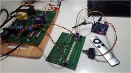
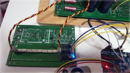
For the past week, I also made your MDAC and it's working perfectly with my Apple remocon and Arduino Uno, also Nano too.
I haven't attached the selector yet, but other things all work well. Thanks you, Maxw.
Now I'm going to check if there are sound coloring and other conditions.
One thing that ask to you is that how I make MDAC with no gain?
As per your comment, it have 12db gain. What resistor should have to removed for no gain??
Nice! To make one without gain you can bridge R3 and remove R2 to make a schematic like the one in this post:
http://www.diyaudio.com/forums/anal...log-switches-multiplying-dac.html#post3488200
maxw said:Like we said before, you should make sure that every relay is working. You will need to write some code to switch each relay individually (1, 2, 4, 8, 16, 32 etc)
Hi Maxw,
Ok I'll check for relay.
But it's seemed that relay working well cause when I rotate the encoder shaft & push the apple remocon, relays make clicking sound immediately.
Also, on the debug screen, it show the step increasing and decreasing....
I'll check the relays pins with my multimeter soon.
(Relay pin 1 is positive voltage, pin 8 is negative voltage. Is it right?)
Last edited:
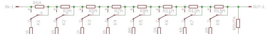
The first relay attenuator is loaded by all that follows.
The clever bit that allows this to work is that everything that follows is always 10k (or your set value).
Look at the first attenuator.
The contact is in the down position.
The first resistor (R1A) is the series resistor of the attenuator.
The lower resistor (R2A?) is a part of the shunting resistor. That shunting resistor AND all that follows are a parallel combination. You calculate that parallel combination and then use that in the normal Series+Shunt ladder attenuator.
When the relay contact moves up the top resistor is bypassed. The Shunting resistor has an open circuit.
Now all that follows is 10k.
If you move to the last relay (K8), exactly the same logic applies. All that follows = 10k etc......
Last edited:
Because it' series connection according to the schematic, even there are no power connection from PSU, there should be a sound from output, isn't it??
Yes. They are latching relays so even without power the last setting will just stay set.
Hi Maxw,
Last night, I tired to check of the each relay's electric connections with multimeter.
I've connect one test probe on the digital ground, and put another probe on the all 8 relays' pin 1 & pin 8 step by step. And increase/decrease with encoder.
It's strange because all relays' pin 1 & 8 show 5V in the same time in every steps even when I decreased/increased volume level... but in every steps, there are still clicking sound without music. (The power is measured 5V(high) on CS & VDD of the board.)
I guess there should be 5V or 0V, even -5V on each relays' 1 & 8 pins as programmed order...Is it matter of the control chips? 😡
Last night, I tired to check of the each relay's electric connections with multimeter. I've connect one test probe on the digital ground, and put another probe on the all 8 relays' pin 1 & pin 8 step by step. And increase/decrease with encoder.
rainwalk, you need to understand more about how it works because this test method will not work. The relays are latching relays so they only need power to change, not constantly.
You can see here:
https://github.com/FutureSharks/preamp-passive/blob/master/preamp-passive.ino#L242-L246
The voltage is only applied to the relay for 1ms, much to fast for you to be able to measure. So the voltage across relay pins 1 and 8 will only be +5V or -5V for 1ms, then it should be 0v.
I'll write you some instructions on how to test later tonight.
OK rainwalk,
Remove everything from in loop() and replace with this:
This should switch every relay on, wait 1 seconds, then switch every relay off. On each relay, measure between these pins:
So that's 4 measurements for every relay. On each measurement you should measure 0 ohm, then NC (connected and then not connected).
Remove everything from in loop() and replace with this:
Code:
setAttenuatorLevel(255);
delay(1000);
setAttenuatorLevel(0);
delay(1000);
This should switch every relay on, wait 1 seconds, then switch every relay off. On each relay, measure between these pins:
- 6 and 5
- 6 and 7
- 3 and 2
- 3 and 4
So that's 4 measurements for every relay. On each measurement you should measure 0 ohm, then NC (connected and then not connected).
Understood more clearly and thank you, Maxw.
In my checking, It's measured +5V between D.GND and pin 1 & 8 constantly.
Not 0V showed.. I thought there something wrong.
But the board is very simple and i check several time of the right soldering...
I'll try your test code tonight and check resistor valus according to your guidance.
Thank you very much!! 😉
Hi rainwalk
Are you sure you have the right controller ?
There are 2 of them the SPI MCP23S17 and the I2C MCP23017
Are you sure you have the right controller ?
There are 2 of them the SPI MCP23S17 and the I2C MCP23017
Hi rainwalk
Are you sure you have the right controller ?
There are 2 of them the SPI MCP23S17 and the I2C MCP23017
Hi RS232,
I used right chip.😉 Thank you.
Completed!!
Hi Maxw,
I'm very pleased let you know that I finally succeed in building your passive attenuator. It's now working perfectly and very good sound.
As per your advice, I have modified the code and test each relay's movement. As a result, I found 2 relays from each board (total 2 board I have already made) were stuck. First time, I changed the one relay. But new relay also stuck. So I added 0 in to your code. 😉
// Function to set a specific attenuator level
int setAttenuatorLevel (byte level) {
muteEnabled = false;
sleeping = false;
currentAttenuatorLevel = level;
if (debugEnabled) {
Serial.print ("Attenuator Level: ");
Serial.println (level);
}
byte real_level = 255 - level;
byte gpioaValue = reverseByte(real_level);
byte gpiobValue = reverseAndMirrorByte(gpioaValue);
setMCP23Sxx(AttenuatorCSPin, 18, gpioaValue);
setMCP23Sxx(AttenuatorCSPin, 19, gpiobValue);
delay(1);
I just change delay(1) to (10). Now... all problem disappear into thin air😀 (ofcourse, Even total 4 realys are gone (I don't know, why...)
Then, everything perfect. I'm really happy becuase it make me confused for several weeks! I don't know why it didn't work with delay time 1 for me, but I hope it could be help to another diyer.
Thank you very much Maxw for your sharing and kind support so far. 😉
Only one thing I want to improve is that volume increase more smoothly.
I guess I need to try with various resistor values. And with my headphone amp, from step 1 to almost step 120~150, volume is too small so make useless 255 steps. I should test it with my preamp (not only for headphone amp) and then study for it later.
Anyway, It's tiny, easy😱 to diy, fantastic performance passive attenuator!! Great! Thank you again.
Attachments

Last edited:
Excellent! Happy you now have it working 🙂Hi Maxw,
I'm very pleased let you know that I finally succeed in building your passive attenuator. It's now working perfectly and very good sound.
Interesting. Maybe I just got lucky with mine and this number should be increased. It should still be as low as possible, does 5ms work for yours too?I just change delay(1) to (10). Now... all problem disappear into thin air😀
And with my headphone amp, from step 1 to almost step 120~150, volume is too small so make useless 255 steps.
Yeah this is somewhat normal and IMO one of the down sides of a passive attenuator: you need some amount of gain after the attenuator to make the range usable.
Also, remember to set debug variable to false when you are done. Otherwise all the serial.print stuff slows the Arduino down.
my experience with the latching relays is that you need either a STRONG power supply to flip the relays over quickly OR you need to give them more soak-time so that they flip over and stay.
if you give it a very solid 5v (btw, I use 4.5v relays) then a few ms time is enough. if your psu is laggy a bit, then increase the soak time.
if you give it a very solid 5v (btw, I use 4.5v relays) then a few ms time is enough. if your psu is laggy a bit, then increase the soak time.
Excellent! Happy you now have it working 🙂
Interesting. Maybe I just got lucky with mine and this number should be increased. It should still be as low as possible, does 5ms work for yours too.
Okay, I'll try it and let you know.
Also, remember to set debug variable to false when you are done. Otherwise all the serial.print stuff slows the Arduino down.
Oh, I forgot! Thank you Maxw!
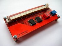
That is one I made years ago. It uses a different IC that uses I2C and also non-latching relays.
I think just power consumption and wear in tear I guess. For example in the datasheet for Omron G6 relays they say:
Using the Relay in a circuit where the Relay will be ON
continuously for long periods (without switching) can lead to
unstable contacts because the heat generated by the coil itself
Probably not an issue in an application like preamp but I guess a latching relay is just a better solution.
Using the Relay in a circuit where the Relay will be ON
continuously for long periods (without switching) can lead to
unstable contacts because the heat generated by the coil itself
Probably not an issue in an application like preamp but I guess a latching relay is just a better solution.
- Home
- Source & Line
- Analog Line Level
- Passive Preamp: Arduino based, remote control, Relay R2R, input selection