just in case it might be the case: have you tried swapping the input end of the atten and the output end?
I have to admit, on my own relay atten, I have sometimes swapped the in/out connections by mistake and the end effect is a strange varying of the volume with big jumps and some steps that don't seem to do much. so, if that describes your situation, see if swapping in/out helps. just in case 😉
I have to admit, on my own relay atten, I have sometimes swapped the in/out connections by mistake and the end effect is a strange varying of the volume with big jumps and some steps that don't seem to do much. so, if that describes your situation, see if swapping in/out helps. just in case 😉
First two is just change all resistors with new? one because I'm not sure if the problems from resistor.
Last one I tired other resistors value.
but all case have same situations. Volume level changed up&down like wave when i turn the encoder turn-right or turn-left, both side are same.... would you check again your code to ensure relay's working in serial?
And input/output of the board.. in my case, i have to change the connection with opposit side. Only the case I put the input-line on output header on the board, sound there..
Last edited:
With same resistor values, it's same condition.
The volume is repeate high & low. From the beginning to end of 256 steps, high & low repeated about 3 times.
With different resistor values, total volume level is low but same condition. High & low repeated.
The volume is repeate high & low. From the beginning to end of 256 steps, high & low repeated about 3 times.
With different resistor values, total volume level is low but same condition. High & low repeated.
Hi Rainwalk,
It's hard for me to say, I don't really understand fully.
But I perhaps try this....
1. Check the resistor values. Are they correct? You have three projects to compare to: Mine, eijndhoven and the AMB. All three projects have the same schematic and part values. Just check you have it correct and then just stop soldering and unsoldering resistors.
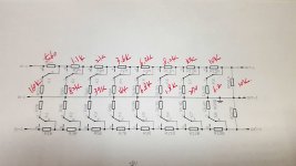
2. Enable debug mode in the arduino code and look at the serial monitor. Is the attenuator value changing as expected? Check each relay, does each activated relay add up in a way that adds up to the correct value? K1=0.5dB, K2=1dB, K3=2dB etc.
3. Read the serial monitor. At what step does it sound in correct? And wrong? What relay would that be? Is it just one? This might help you narrow down the issue.
4. Is the device after the attenuator a high impedance device? i.e not headphones?
5. Why don't you use a multimeter to measure while making changes? This could help you work out where the problem is. It's just a load of switches and resistors, you have the schematics, you can change the code to set any relay to any value. You could set each relay individually by setting just setting the level to 1dB, 2dB, 4dB, 8dB, 16dB, 32dB etc.
That's about all I can suggest.
It's hard for me to say, I don't really understand fully.
But I perhaps try this....
1. Check the resistor values. Are they correct? You have three projects to compare to: Mine, eijndhoven and the AMB. All three projects have the same schematic and part values. Just check you have it correct and then just stop soldering and unsoldering resistors.
2. Enable debug mode in the arduino code and look at the serial monitor. Is the attenuator value changing as expected? Check each relay, does each activated relay add up in a way that adds up to the correct value? K1=0.5dB, K2=1dB, K3=2dB etc.
3. Read the serial monitor. At what step does it sound in correct? And wrong? What relay would that be? Is it just one? This might help you narrow down the issue.
4. Is the device after the attenuator a high impedance device? i.e not headphones?
5. Why don't you use a multimeter to measure while making changes? This could help you work out where the problem is. It's just a load of switches and resistors, you have the schematics, you can change the code to set any relay to any value. You could set each relay individually by setting just setting the level to 1dB, 2dB, 4dB, 8dB, 16dB, 32dB etc.
That's about all I can suggest.
With same resistor values, it's same condition.
The volume is repeate high & low. From the beginning to end of 256 steps, high & low repeated about 3 times.
With different resistor values, total volume level is low but same condition. High & low repeated.
when you say that you have some 'ranges' and then it resets, that, to me, sounds like a stuck bit. a relay that does not go on or off, just stuck one way.
do the 'walking bits' thing like was suggested a few posts ago and you should hear each relay change states. put a second or two between each relay 'walk' step so you can hear if it goes on and off.
Hi linuxworks,
Would you let me konw some details that how & what should I do to prevent relay stuck?? 🙂
Hi Rainwalk,
1. Check the resistor values. Are they correct? You have three projects to compare to: Mine, eijndhoven and the AMB. All three projects have the same schematic and part values. Just check you have it correct and then just stop soldering and unsoldering resistors.
Hi Maxw,
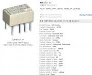
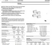
would you check my resistor values based on your BOM?
I also check with AMB value, but it's looks very different.... 😕
Attachments


Last edited:
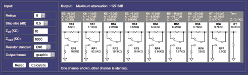
These calculators assume the load is a fixed value.
You set that value as an input. Rload
When you come to connect your attenuator into your system, the attenuator sees the input impedance of the Receiver.
You must insert a resistor to ensure the attenuator sees the impedance you asked for at the design stage.
Suppose you wanted 10k as your Rload.
The input impedance of your receiver is 47k
You fitted a 10k resistor to the attenuator.
The attenuator sees a load of 10k||47k = ~8k25
That loading resistor really needs to be selectable to suit the input impedance of the Receivers you may want to use.
For various impedances you could have a stepped final resistor.
for 10k Rload
Input Z . . Rload
100k. . . . 11k111
50k . . . . . 12k500
47k . . . . . 12k703
22k . . . . . 18k333
20k . . . . . 20k
10k . . . . . open
Change Zatt in amb's calculator to 10k... You are comparing your 10k values with amb's 25k...
Thanks! I updated the captured.
I'm not sure this input is right or not. 😕
Attachments
Last edited:

You have inserted 10000kohmsThanks! I updated the captured.
I'm not sure this input is right or not. 😕
That equals 10M
You should have inserted 10kohms
Last edited:
Zload of 1000kohms is unreasonable.No.
Zatt is 10.
Zload leave as default 1000.
That is the values I used. Same as the eijndhoven.
Use a value that is likely to be attached, somewhere from 10k to 100k
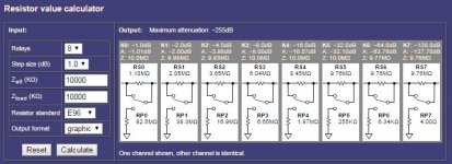
Note that the left calculator assumes a 10k Rload
The right hand calculator tells you what resistor is required to adjust your Zin to match your required Rload.
Last edited:
Yes true but it doesn't matter, it only changes the Zload resistor. You can change this to suit your next stage as you wish but I don't think it's part of rainwalk's problems.
It does matter, the relay attenuations only work accurately when each relay is loaded with the specified load.
You ask for a 10k relay attenuator and all the calculations assume that this load is actually attached. Each relay presents that specified impedance to the preceding circuits when that relay is also loaded to the specified impedance. The last impedance (that fixed resistor) must be the Rload. The right hand calculator shows 10k2 to be used in parallel to 1000k to give the 10k1 shown in the box above.
Had they actually used 10k1 || 1000K then the impedance would be ~9k99901
No.
Zatt is 10.
Zload leave as default 1000.
That is the values I used. Same as the eijndhoven.
Hi Maxw & all
Thank you very much for kind advises.
Hmm... now I thought the resistor values are no problems. But why It's still not working...😕 I'll try to check others include your previous advise continuously (except arduino code...I need to study) and if you don't mind, I'll keep asking you. 🙂
Anyway, there is one good news.
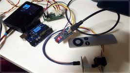
For the past week, I also made your MDAC and it's working perfectly with my Apple remocon and Arduino Uno, also Nano too.
I haven't attached the selector yet, but other things all work well. Thanks you, Maxw.
Now I'm going to check if there are sound coloring and other conditions.
One thing that ask to you is that how I make MDAC with no gain?
As per your comment, it have 12db gain. What resistor should have to removed for no gain??
Attachments
You have inserted 10000kohms
That equals 10M
You should have inserted 10kohms
Woops! I misunderstood as ohm..😱
- Home
- Source & Line
- Analog Line Level
- Passive Preamp: Arduino based, remote control, Relay R2R, input selection