1)The reflected waves of drivers using 4 times the chamber size will be four times longer, the issue is the same, but the effect is worse, and instead of single mode reflections, they are multiplied by 4 in a quad cabinet. A pair of my FLH L2 cabinets (one driver per chamber) sounded better than a functionally similar L4, in which 2 drivers shared a chamber on either side. I don't just make this stuff up as I go along, I experienced it back when I still had hearing good enough to hear subtle differences ;^).
I'm not suggesting you are making it up.
I'm not sure what you mean by "single mode reflections" but in this case the overall dimensions of a single large vs 4 individual chambers are not that different, the volume is definitely the same and any one dimension isn't going to be 2x larger. Definitely not 4x larger unless you count a wave that goes all the way around the inside of the chamber, in which case it will have had to reflect several times and won't be very strong.
And the dimensions are EXTREMELY small compared to the frequency wavelengths inside the passband so resonances definitely are not an issue.
If you are talking about a simple reflection bouncing off the chamber walls and messing with the cones, that's not really an issue either. At these dimensions it's all about pressure, any reflections that could generate any type of interference would be at much shorter wavelengths that are not inside the passband.
I'm not familiar with L2 and L4 subs and how "functionally similar" they might be. If the difference is more than a panel dividing the chamber into two separate sealed chambers instead of one larger chamber the audible differences you noted could have been from countless other factors.
2) The failure mode I described had nothing to do with stress or abuse, the tinsel lead crimps were simply defective ...
Ok, this is something completely different. In your own words the drivers were defective. If we are going to go about designing based on the fact that the drivers might be defective the design is going to change a lot - and since defective drivers can fail in many different ways, if you are anticipating an unknown failure the design will have to be completely bulletproof in all ways.
I have to admit I've never designed based on the assumption that the drivers might be defective. If the drivers fail the fail mode should be determined and dealt with - by using different drivers if necessary. Which means replacing them all. What's the point of continuing to use defective drivers if you already know they are defective and you know the fail mode? Unless it's a warranty situation and you are absolutely unwilling to correct the fail mode it makes more sense to pick drivers that are not defective and replace them all.
Last edited:
Hi,
I suggest using the woofers mounted to stubs in pairs, with the stubs joining in a common throat. This would allow for cancellation of opposing forces, and if desired for PP mounting as well as PPSL mounting.
Regards,
I suggest using the woofers mounted to stubs in pairs, with the stubs joining in a common throat. This would allow for cancellation of opposing forces, and if desired for PP mounting as well as PPSL mounting.
Regards,
I'll leave the HR horn simming to others more skilled in the HR art 😉
I think it "Could" be beneficial because, it could reduce the amount of drivers needed due to the gain @ fb, and/or reduce Xmax & distortion due to same, for a given drive level compared to not porting.
Might be a good time to try 🙂
Of course, but lets say it's done right !
Well he's into concrete 😀 so that shouldn't be a problem ! But it "could" be less huge, with the port not as long/wide. Anyway, there would be More than enough room in that massive horn to fit it.
I think it "Could" be beneficial because, it could reduce the amount of drivers needed due to the gain @ fb, and/or reduce Xmax & distortion due to same, for a given drive level compared to not porting.
Originally Posted by just a guy
I admit I've not done much (or any) work on chambers ported into horns because I see no need
Might be a good time to try 🙂
and if it's not done right it can do way more harm than good.
Of course, but lets say it's done right !
Anyway, if the back chamber is tuned to 20 hz it either needs to be HUGE or it needs a HUGE (very long) port. And unless it's HUGE there's not going to be any significant resonance, so not much benefit.
Well he's into concrete 😀 so that shouldn't be a problem ! But it "could" be less huge, with the port not as long/wide. Anyway, there would be More than enough room in that massive horn to fit it.
Hi,
Normally, the closed rear chamber would be for impedance matching the horn mouth. With something this size the overall horn load is so high that the chamber size does not make much of a difference once you get past the point where the chamber is clearly too small (cutting of lows, and creating ripple).
Against my better judgement I'm posting the simulation I used in Post #235, this time w/ the normal Vrc=340L and a comparison w/ Vrc @ 34000L. If you are concerned about tuning chambers, it would be the throat chamber Vtc, which interacts w/ the horn to form a low pass filter which can be used as a mechanical filter to reduce the upper output of the horn. (Actually, you could leave the speaker backs open, and the horn would still woof just fine. -) )
Regards,
Attachments
Have you simulated the effect of the slightly different t/s from horizontal vs vertical position? It doesn't add up to much.
I didn't bother, because when I've simulated the effects of similarly small changes (driver warmed up with test tones versus cold driver), they were measurable, but, as you say, didn't add up to much.
If it was my bucket list project*, I'd consider any small improvement, if implementing that improvement had no downside.
A small screen would do the same, most compression tweeter have a screen.
Yep. Or both. A vertical horn section would probably keep out dust, rats, snakes etc, but on my property, I'd still get creatures (wasps, spiders**, possibly birds) nesting and dying in the throat. I assume that Entropy would have some equivalent fauna near Seattle.
Agreed, but I'd say a low level of problem; enough so that I'd only chase it for a perfectionist project.Anyway, some drivers are infamously bad at sag issues, some have no problems. I think OP's chosen driver will probably fall in the latter camp.
* I went through a similar planning process a few years ago, when I was building a sound system into an industrial / living space. After I modeled a bunch of huge, J-shaped 1/4 space bass horns, I eventually went with a smaller, 1/8 space IB array - it wasn't a bucket list project.
**including huntsmen like this guy, famous for being big enough to eat a mouse.
Huntsman spider drags mouse to grisly end in central Queensland - ABC News (Australian Broadcasting Corporation)
Last edited:
I'll leave the HR horn simming to others more skilled in the HR art 😉
I think it "Could" be beneficial because, it could reduce the amount of drivers needed due to the gain @ fb, and/or reduce Xmax & distortion due to same, for a given drive level compared to not porting.
I think you might be overestimating what you can get out of a relative small ported box compared to a 30000 liter horn, but curiosity always does me in so ...
Might be a good time to try 🙂
Fine. Are you sitting comfortably? Then we'll begin.
I didn't go all the way with this for reasons that will become very obvious, but I've got enough information here to get you started if you feel like carrying on.
First I had to figure out HOW to do this. The new multiple entry tool sounded promising (I haven't used it yet) but I don't think it will do quite what I want.
So I was stuck with the "horn loaded vented box enclosure with port exit located inside the horn mouth", which is adequately described in Hornresp Help.
So we need a baseline to judge our efforts against. The baseline is OP's original design (for now, I guess, as he hasn't updated us with anything new yet) so here is the original design.
An externally hosted image should be here but it was not working when we last tested it.
Then I used the "hypex approximator" tool to cut it into 4 segments. This is necessary because the only way to simulate this is as a tapped horn and we don't want the port firing into the horn mouth, we want it firing directly into the throat.
So the first 3 segments are just 0.01 cm long and they are only there because the port needs to fire into S4 in a tapped horn like this. Normally the port could fire into S3 in a tapped horn, but this particular horn is too big, S4 cannot be greater than 99999.99 sq cm. This leads to 3 segments at 0.01 cm length each just there so the sim will run.
The 4th segment is basically the entire horn in a single pure EXP segment, and the only reason this works is because OP's sim was already so close to a pure EXP segment. His hyp/ex T was 0.93 which is very close to pure exponential, so changing it to an EXP segment doesn't change much at all. Overall the horn gained 350 liters in the flare itself from this change but that's like 1 percent gain, basically nothing. And the frequency response and excursion changed ever so slightly but it's not a big deal.
Just to make sure I was on the right track at this point I reran the sim to compare the chopped up horn to the original horn - the new horn frequency response and excursion is in black, overlaid on the old horn data in light grey.
An externally hosted image should be here but it was not working when we last tested it.
So at this point we're already not exactly the same but there's nothing I can do about that if I want to run this ported rear chamber sim.
The next step is to turn it into a TH sim and add a port (fill in Ap and Lpt). Initially I tried a 200 sq cm port (because I want it fairly big for velocity issues, and I'm not sure if the "Particle Velocity - Tapped Throat" tool is giving me the velocity at the actual throat or in the port. I'd need to run Akabak to find out (or maybe David can let me know).
Then I used the "Calculate Lpt" tool to tune the 295 liter chamber to 20 hz, this gave a port length of 39.06 cm IIRC. And I ran the sim. The results were not pretty. So I tried to open the sim in the Loudspeaker Wizard so I could use the sliders and make the iterative process of changing the chamber volume and port length quick and easy and I got this.
An externally hosted image should be here but it was not working when we last tested it.
Lovely. So no Loudspeaker Wizard for me.
I made a few changes and I did get a kinda usable result but I'm not sure if this is even close to as good as it can get (because I'm not going to plug different chamber volume and port length numbers in all day and hit calculate and do this the old slow way) and I'm not sure that what I've achieved is any kind of benefit. Sure, the ported rear chamber does give the horn a little kick in the *** in the low knee and even moves the low knee down in frequency a couple hz, but it also subtracts a bit of spl above the low knee AND it requires a bit more excursion above the low knee for that slight loss of spl.
The interesting thing is that to get this result I actually had to shrink the rear chamber - a lot. Because I wasn't getting pretty results with the original chamber size. But then again I didn't try more than a dozen combinations of rear chamber size and port length.
So here's the sim if anyone wants to play with it, and hopefully David can let me know why I get a run time overflow error.
An externally hosted image should be here but it was not working when we last tested it.
And just for fun here's an overlay of the ported rear chamber horn vs the original horn.
An externally hosted image should be here but it was not working when we last tested it.
So that's the situation, take the ball and run with it. As for me, I don't see any great benefit yet to porting the rear chamber into the throat. And I'm not going to do much work on this unless the Loudspeaker Wizard is accessible. I have a feeling that the mouth is too big to open in the Loudspeaker Wizard, if so there's not much that can be done other than do the iterative changes the old slow way, which I'm not excited about because this is not my project and I was never interested in porting rear chambers into horn throats in the first place.
So if David reads this, to recap, my issues here were -
1. There should be a better way to do this than use a TH model, as that uses up the first 2 (or in this case 3) segments just to get the sim to run, then you only have 2 (or in this case 1) segment left to define the actual horn flare. Maybe a slight mod to the "multiple entry tool would allow this kind of sim more easily (or maybe it already does and I just don't know how to use it, but I don't think so.)
2. S4 can't be greater than 99999.99 sq cm. Can we eliminate this limit? It would have allowed me 2 segments (instead of 1) to define the horn flare, not that it would have made a lot of difference in this case, but more flexibility is always better.
3. The run time overflow error - is this just because the horn is too big for the Loudspeaker Wizard or what's up with this?
4. Is the "Particle Velocity - Tapped Throat" tool giving me the throat velocity or the port velocity? Because I couldn't care less about the throat velocity but I care very much about the port velocity and there's nothing in the menu labeled "Particle Velocity - Port".
Last edited:
1. There should be a better way to do this than use a TH model, as that uses up the first 2 (or in this case 3) segments just to get the sim to run, then you only have 2 (or in this case 1) segment left to define the actual horn flare. Maybe a slight mod to the "multiple entry tool would allow this kind of sim more easily (or maybe it already does and I just don't know how to use it, but I don't think so.)
2. S4 can't be greater than 99999.99 sq cm. Can we eliminate this limit? It would have allowed me 2 segments (instead of 1) to define the horn flare, not that it would have made a lot of difference in this case, but more flexibility is always better.
3. The run time overflow error - is this just because the horn is too big for the Loudspeaker Wizard or what's up with this?
4. Is the "Particle Velocity - Tapped Throat" tool giving me the throat velocity or the port velocity? Because I couldn't care less about the throat velocity but I care very much about the port velocity and there's nothing in the menu labeled "Particle Velocity - Port".
Actually after having a quick smoke break there is something I can do to eliminate at least one of these issues, and maybe two of them.
I could sim the horn in 1 pi or even 0.5 pi and accordingly reduce the horn size by a factor of 2 or 4, which would give the same results and definitely solve issue #2 and probably solve issue #3 while still giving the same results. I'll try this later.
But I would still like an answer to #1 and #4 if anyone knows if there's a better way to sim a sealed rear chamber ported into a horn throat (if there is an better and easier way that's escaped me I'll feel pretty dumb) and what exactly the "Particle Velocity - Tapped Throat" tool is showing, because I need the port velocity info, not the throat velocity info.
Post 252
Post 243
Some Orwell:
The possibility of driver failure shouldn't be an issue, as GM points out. OP wants the lowest possible distortion so he shouldn't be pushing his drivers anywhere near xmax and the power each driver will see is extraordinarily low.
Post 243
if all the drivers are sharing the same sealed chamber. If half of them aren't working they likely won't "feel" the same loading and you could very well shoot right past xmax and damage the drivers, since the sealed chamber size has effectively doubled.
Some Orwell:
There was, of course, no admission that any change had taken place. Merely
it became known, with extreme suddenness and everywhere at once, that
Eastasia and not Eurasia was the enemy [...]
The thing that impressed Winston in looking back was that the speaker had
switched from one line to the other actually in midsentence, not only
without a pause, but without even breaking the syntax.
The rear wave has to be addressed, perhaps sequested, as with many other kinds of box*. What's nice about a true horn is that it is geometrically and acoustically natural to introduce a sealed box in the rear.** Because of the radiation resistance (and compression) loaded on the front of the cone, the box can be rather small. With a sealed box behind the cone, you collect all the fidelity benefits of sealed box enclosures.
Once again, thousands of words devoted to "the trees" instead of a few moments of thought about "the forest".
Ben
*Dipoles in a typical home music room may not be sticky about the theory.
**once you figure out how the heck to get the driver in there... one of Paul Klipsch's accomplishments
Once again, thousands of words devoted to "the trees" instead of a few moments of thought about "the forest".
Ben
*Dipoles in a typical home music room may not be sticky about the theory.
**once you figure out how the heck to get the driver in there... one of Paul Klipsch's accomplishments
Last edited:
What's nice about a true horn is that it is geometrically and acoustically natural to introduce a sealed box in the rear.
What on earth are you talking about now? Of course it's acoustically natural to have a rear sealed chamber. How do you think reactance annulling occurs? Do you even know what reactance annulling is?
And it's not just natural, it's easy and well defined. There are several horn math models floating around that will size the rear chamber for you. Or if you decide to design the whole system at once (the ideal driver parameters and the ideal horn), the rear chamber size is one of the variables that you have to personally define so the math can commence.
Because of the radiation resistance (and compression) loaded on the front of the cone, the box can be rather small.
The horn math model is not a "one size fits all" static dumb equation. When you run the equations for an ideal horn for a given set of driver parameters for a given desired low knee frequency and desired gain bandwidth the rear chamber MIGHT end up too small to fit the driver and the compression ratio MIGHT end up unrealistically high.
This is of NO CONSEQUENCE WHATSOEVER. There are two solutions to this issue.
1. Pick a different driver that has better matched t/s specs for your desired low knee frequency and gain bandwidth.
2. Pick a different target low knee and/or gain bandwidth. Making the target gain bandwidth narrower by an octave doesn't change the response of the horn much but it will drastically increase the ideal rear chamber size and decrease compression ratio.
Once again, thousands of words devoted to "the trees" instead of a few moments of thought about "the forest".
Once again you are proving you have no concept of what is involved in horn math and theory. You already admitted you don't know anything about it when OP asked for your input. Now you are trying to imply that none of us know anything about it.
If you would actually read the horn theory and work through the math you would see how this stuff actually works. You don't even have to know the math, Hornresp can do it for you. And the math model it uses is Leach's from the paper "On the specification of moving coil drivers for low frequency horn loaded loudspeakers".
I can absolutely assure you that the math and theory are not inflexible, rear chamber size depends directly on driver t/s, desired low knee and desired gain bandwidth. All of these factors can be adjusted, so if the rear chamber is too small it's completely the fault of the designer's stupidity. He has either picked the wrong driver for the job or the wrong design goals for a given driver.
Furthermore, if the designer wants to have a MASSIVE rear chamber size, the software will allow that and give the most ideal horn dimensions to accommodate that misguided design goal.
In this particular discussion, the horn design presented was created using horn math and theory and the chamber size is 295 liters for five 12 inch drivers. That's hardly a small chamber.
So in conclusion I have no idea what you are trying to prove here. Some of us have a pretty good grasp on the horn math and theory.
With a sealed box behind the cone, you collect all the fidelity benefits of sealed box enclosures.
I know EXACTLY where you are going with this, as you've brought it up a couple hundred times over the years. You think the sealed rear chamber means the horn is acting like a sealed box but with massive gain. This is not the case. The massive gain is due to a bunch of resonances inside the passband. If the horn is not designed well, and especially if it's massively undersized, it will have none of the fidelity benefits of sealed box enclosures. Take the Klipshhorn for example. I've never seen a nice measured frequency response from that antique, it's riddled with ugly resonant spikes all through the passband. It's garbage by today's standards.
Last edited:
Post 252
Post 243
...
Truth be told though, it isn't even that much of a danger, the excursion doesn't increase THAT much if half the drivers are not working. Sometimes I exaggerate a bit to make a point. Even the change in frequency response if half the drivers aren't working isn't a huge change.
My main objection is that things WILL change if the signal is panned hard to one side or half the drivers fail - the 3 db difference you noted is only one of the several things that change. The amount of change is something I would consider unacceptable but what people are willing to put up with is always a personal subjective judgement call.
The quick and easy solution would be to use the mono summing capabilities that are already present in the electronics that are going to be required to run the system, not playing games wiring half the drivers to different amp channels or using DVC drivers to essentially do the same. The signal should be full mono before it ever gets to the drivers. With modern electronics there's no reason to do it any other way, the capability is already built in.
My main objection is that things WILL change if the signal is panned hard to one side or half the drivers fail
That's two entirely different scenarios. In the first the driver's motors are still connected to the amplifier; in the other they are not.
I was reading this thread last night with the lights off and I saw the wall beside me move. Soon I noticed it was just Harry.**including huntsmen like this guy, famous for being big enough to eat a mouse.
Hi just a guy,
Another one for AkAbak 🙂.
It's not going to happen 🙂.
It's because you used the original version of the Hypex Approximator tool which accepts area values greater than 99999.99 sq cm. See the post linked below.
http://www.diyaudio.com/forums/subwoofers/119854-hornresp-666.html#post4835745
It is giving you the peak particle velocity at the port exit (i.e. at the S2 tap entry point). I will look at making this a bit clearer in the Help file.
Kind regards,
David
1. There should be a better way to do this than use a TH model, as that uses up the first 2 (or in this case 3) segments just to get the sim to run, then you only have 2 (or in this case 1) segment left to define the actual horn flare.
Another one for AkAbak 🙂.
2. S4 can't be greater than 99999.99 sq cm. Can we eliminate this limit?
It's not going to happen 🙂.
3. The run time overflow error - is this just because the horn is too big for the Loudspeaker Wizard or what's up with this?
It's because you used the original version of the Hypex Approximator tool which accepts area values greater than 99999.99 sq cm. See the post linked below.
http://www.diyaudio.com/forums/subwoofers/119854-hornresp-666.html#post4835745
4. Is the "Particle Velocity - Tapped Throat" tool giving me the throat velocity or the port velocity?
It is giving you the peak particle velocity at the port exit (i.e. at the S2 tap entry point). I will look at making this a bit clearer in the Help file.
Kind regards,
David
JAG,1)I'm not suggesting you are making it up.
And the dimensions are EXTREMELY small compared to the frequency wavelengths inside the passband so resonances definitely are not an issue.
If you are talking about a simple reflection bouncing off the chamber walls and messing with the cones, that's not really an issue either. At these dimensions it's all about pressure, any reflections that could generate any type of interference would be at much shorter wavelengths that are not inside the passband.
2) If we are going to go about designing based on the fact that the drivers might be defective the design is going to change a lot - and since defective drivers can fail in many different ways, if you are anticipating an unknown failure the design will have to be completely bulletproof in all ways.
I have to admit I've never designed based on the assumption that the drivers might be defective. If the drivers fail the fail mode should be determined and dealt with - by using different drivers if necessary. Which means replacing them all. What's the point of continuing to use defective drivers if you already know they are defective and you know the fail mode? Unless it's a warranty situation and you are absolutely unwilling to correct the fail mode it makes more sense to pick drivers that are not defective and replace them all.
1) Yes, like harmonic distortion, the type of distortion generated by reflections passing through cones is not in the pass band, which makes it more sonically obvious, thanks for the explanation.
2) If you had experienced driver failures, and understood how debilitating they can be, perhaps you would be more inclined to design based on the possibility of failure.
I "deal with" defective drivers by replacing them. In the particular series of tinsel lead failures I recounted, there was no way of telling if the failure was isolated (I had never had an Eminence driver fail without any sign of abuse before) and whether any other drivers would fail other than when they did.
I didn't "pick" defective drivers, at the time LAB 12s had been out several years, and the two failure modes I had heard about with them were typical of any drivers pushed beyond mechanical limits (usually from air leaks in the compression chamber) or thermal (cooked voice coils from too much average power).
There was no way for me to "correct the fail mode" other than replacement. The fact that the drivers failed within the warranty period saved repair costs, but would have been bad for business if the failed driver had messed up working drivers as it would have if the drivers shared a box.
Knowing Eminence, they probably would have repaired the manufacturing defect for no cost even if out of warranty, unlike some other companies.
I purchased two Sennheiser MD421 II microphones to meet the Jazz Crusader's equipment rider. They showed up with their own microphones, so I did not use the new 421s on that show, and only used them a few times on brass instruments, they saw no abuse by drummer's errant sticks or high air velocity from sticking them in a kick drum hole. Slightly after the 1 year warranty, both of the new microphones failed, the mark II version of the 421 had a reduced diameter voice coil for better "transient detail", the voice coil wire, similar in diameter to a human hair, had opened up somewhere, for no reason other than a manufacturing defect.
Sennheiser was sorry about the failures, and offered to to replace the diaphragms for a few dollars less than I paid for the vastly overpriced microphones.
That dead pair of MD421 II will likely be the last Sennheiser microphones I will ever purchase, though I still have a pair of 421 built around 1962 that work perfectly, and have never been "babied" like the pair that failed.
Gotta move on...
Art
That's two entirely different scenarios. In the first the driver's motors are still connected to the amplifier; in the other they are not.
Yes, I realize that, that's why I specifically mentioned both scenarios. In the first the drivers will resist being pushed around, in the other they will not, acting somewhat like passive radiators. Neither situation is good, which is why I mentioned both.
Hi just a guy,
Another one for AkAbak 🙂.
It's not going to happen 🙂.
Oh well, you win some you lose some. I guess my favorite programmer has no Christmas presents for me this year. As I mentioned I already have a workaround in mind.
It is giving you the peak particle velocity at the port exit (i.e. at the S2 tap entry point). I will look at making this a bit clearer in the Help file.
Kind regards,
David
This would be very useful but it would be even more useful if it specifically said in the menu "Particle Velocity - Port". Then it wouldn't be necessary to visit the Help file for clarification. I'm not sure if this is possible or not.
JAG,
1) Yes, like harmonic distortion, the type of distortion generated by reflections passing through cones is not in the pass band, which makes it more sonically obvious, thanks for the explanation.
2) If you had experienced driver failures, and understood how debilitating they can be, perhaps you would be more inclined to design based on the possibility of failure.
I "deal with" defective drivers by replacing them. In the particular series of tinsel lead failures I recounted, there was no way of telling if the failure was isolated (I had never had an Eminence driver fail without any sign of abuse before) and whether any other drivers would fail other than when they did.
I didn't "pick" defective drivers, at the time LAB 12s had been out several years, and the two failure modes I had heard about with them were typical of any drivers pushed beyond mechanical limits (usually from air leaks in the compression chamber) or thermal (cooked voice coils from too much average power).
There was no way for me to "correct the fail mode" other than replacement. The fact that the drivers failed within the warranty period saved repair costs, but would have been bad for business if the failed driver had messed up working drivers as it would have if the drivers shared a box.
Knowing Eminence, they probably would have repaired the manufacturing defect for no cost even if out of warranty, unlike some other companies.
I purchased two Sennheiser MD421 II microphones to meet the Jazz Crusader's equipment rider. They showed up with their own microphones, so I did not use the new 421s on that show, and only used them a few times on brass instruments, they saw no abuse by drummer's errant sticks or high air velocity from sticking them in a kick drum hole. Slightly after the 1 year warranty, both of the new microphones failed, the mark II version of the 421 had a reduced diameter voice coil for better "transient detail", the voice coil wire, similar in diameter to a human hair, had opened up somewhere, for no reason other than a manufacturing defect.
Sennheiser was sorry about the failures, and offered to to replace the diaphragms for a few dollars less than I paid for the vastly overpriced microphones.
That dead pair of MD421 II will likely be the last Sennheiser microphones I will ever purchase, though I still have a pair of 421 built around 1962 that work perfectly, and have never been "babied" like the pair that failed.
Gotta move on...
Art
As I mentioned, I don't design based on the possibility of defective drivers, as they can fail in so many different ways. If there's a glue failure you might as well not use a horn at all so you can have the drivers visible and easily replaceable at all times. For example you might not even notice a failing glue joint at the surround until the surround is halfway unattached and things start to sound funny.
You've mentioned two fantastically defective products now, and I admit, some products are defective, but if you let that determine your design you'll end up with a simple sealed box with temperature and pressure sensors and a remote camera connected via wifi to your laptop so you can keep an eye on the drivers at all times.
In this case it's easy enough to just build separate rear chambers for each driver. I don't think it's necessary because I can't imagine any situation where the drivers would fail unless they were outright defective or EXTREMELY abused but it certainly isn't going to hurt anything either. So go ahead, design for separate rear chambers.
@ just a guy
Hi, Thanx for the sim etc 🙂 i will try & have a tinker with it later 😉
Porting into the throat was not how i envisaged it though. I "think" the extra air pressure into the throat "might" not be a good idea ! Could you try & sim the port external to the horn for now, just to see what difference that "could" make ? I have a feeling it should be better.
*
Re - My WinISD Gloss info
I only linked to older WinISD-Pro as a help file is included with it. The newer version doesn't have a help file yet !
Porting into the throat was not how i envisaged it though. I "think" the extra air pressure into the throat "might" not be a good idea ! Could you try & sim the port external to the horn for now, just to see what difference that "could" make ? I have a feeling it should be better.
Well I'm glad you have optimistic feelings but I think the reality will disagree with you. I told you, the extra output you get from a 295 liter ported box added to a 30000 liter horn isn't going to do much of anything.
But sure, I can sim it, it's super easy. Just take your horn sim and then fill in Ap and Lpt and it's off to the races.
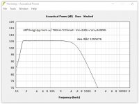
Here's a few different port lengths. I didn't change the rear chamber volume, it's 295 liters in all of these. All I changed was the port length. (In all cases the port cross sectional area or Apt is 200 sq cm.)
First row left - 39.06 cm port tuned right to 20 hz
First row right - port shortened to 11 cm just so you can see what happens
Second row - port lengthened to 55 cm
Third row - frequency response and excursion with 100 cm port
In each case the response is overlaid on top of the original (unported) horn response.
An externally hosted image should be here but it was not working when we last tested it.
So it's pretty clear to see that you can't tune the rear chamber to the exact low knee frequency and you can't tune it above the low knee frequency. It has to be tuned somewhat below the low knee, and even when that is done the "extra" spl just isn't there because the chamber isn't large enough to have output that can compete with what's going on in the horn flare.
Just for an extra wrench in the works, all these sims assume the ported rear chamber and the horn mouth are equidistant from the listener. This sim can't actually reflect the reality of the situation as it is if the horn is not folded because if the horn is straight the only place this sim would be addressing is off to the side (perpendicular to the horn's length midpoint, not in front of the horn) and then it wouldn't be accurate because the horn has significant directivity. So to make the sim truly reflect reality you need to adjust the offset of the port so it's the length of the horn further away from the listener (which is easy to do, I just didn't bother because no matter what you do the ported rear chamber isn't going to add anything unless you make the chamber so large that it can compete with the horn, in which case the horn design will be screwed up).
Incidentally, this is why the burning man horn is such a joke - he ported the rear chamber with no idea what effect it would have. It's not clear if he ported it into the throat or to the outside of the flare, but either way, if it's not done just right it will make things a lot worse, not better.
Last edited:
- Home
- Loudspeakers
- Subwoofers
- Concrete Bass Horn Design Question