I think he had a good match on his input transistors. 2.5mV is pretty spectacular offset with no adjustment. I remember pulling the servo on mine back when I was first trying to sort it out and I had a fairly high offset too.
I'm in the middle of building a preamp and amp for my son so my bench is buried. I will try to find time to hook up my Symasui and see what it is doing. It seems that the servo wouldn't have to do anything if the initial offset is only 2.5mv. I wonder if there is a cap that is pulling the servo off while it charges.
I think C12 would be the one that would charge slowly, but I think the math works out to a second to charge if I understood Valery correctly.
Hi Valery,
thanks for the info.
Sorry, I lost the overview in so many post and was not able to find my first post 😉.
Makes it sens to build the NS-OPS only with 1 or 2 output pairs to get the idle current down?
thanks for the info.
Sorry, I lost the overview in so many post and was not able to find my first post 😉.
Makes it sens to build the NS-OPS only with 1 or 2 output pairs to get the idle current down?
Hi Valery,
thanks for the info.
Sorry, I lost the overview in so many post and was not able to find my first post 😉.
Makes it sens to build the NS-OPS only with 1 or 2 output pairs to get the idle current down?
Hi Ampi,
Well - it all depends on particular requirements.
What sort of maximum power per amplifier channel do you have in mind?
What is the speaker minimal impedance (I'm mostly interested in LF section)?
Hi Valery,
I'am thinking about a "normal" Setup.
tweeter: AirMotionTransformer
mid: wavecor wf120bd or wf152bd
bass: 2*TIW200XS
So minimum impedance sould be 4 Ohms.
In my opinion especially the tweeter or the mid don't need so much power.
So the task would be to design a smaller pcb with one or two pairs transistors in the outputstage.
Hi Valery,
I'am thinking about a "normal" Setup.
tweeter: AirMotionTransformer
mid: wavecor wf120bd or wf152bd
bass: 2*TIW200XS
So minimum impedance sould be 4 Ohms.
In my opinion especially the tweeter or the mid don't need so much power.
So the task would be to design a smaller pcb with one or two pairs transistors in the outputstage.
Yes, in this case 2 pairs will be enough. I recommend MT-200 devices - good current provision capability.
Why are you trying to minimise the idle current? 70mA per output pair is pretty low already. It runs cool enough, you can't really save on PSU as you have to keep it capable driving the rated power... so - what's the point?
Servo experiments.
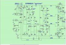
Today i have try to modify the servo controller as this schematic.
What i found?
Using TL072 servo started from 3v and ended up (after 12'')at 24mv!
Using LF412 servo started from 3v and ended up (after12'')at 2.5mv!
I will try the Valery mofification soon.
Today i have try to modify the servo controller as this schematic.
What i found?
Using TL072 servo started from 3v and ended up (after 12'')at 24mv!
Using LF412 servo started from 3v and ended up (after12'')at 2.5mv!
I will try the Valery mofification soon.
Attachments
the 411 is better for servo duty than the 072
It's what was recommended 20years ago and probably long before that.
But why does the amp try to start with only 2.5mVoffset and move to 3Voffset to come back slowly to 24 or 2.5mVoffset?
That's what you have to find out.
Something is going wrong during start up.
It's what was recommended 20years ago and probably long before that.
But why does the amp try to start with only 2.5mVoffset and move to 3Voffset to come back slowly to 24 or 2.5mVoffset?
That's what you have to find out.
Something is going wrong during start up.
Last edited:
I will try to remove this and see what happen then😉Could this be from C12 slowly charging on power up?
Could this be from C12 slowly charging on power up?
C12 is connected to Power Ground on one side and via 470k+Speaker to Power Ground on the other side.I will try to remove this and see what happen then😉
If the speaker is open circuit there is an alternative path to Power ground via R24 - R25 - R3
During power OFF C12 should be completely discharged.
At Power ON it should not acquire a charge. Where would that charge come from?
Last edited:
Could this be from C12 slowly charging on power up?
The question is - what makes the output jumping to 3V with the servo in place - as no-servo test showed, it starts at 2.5mV and stays there, right?
Yes,the no servo version start from 2.5mv and stays there😕The question is - what makes the output jumping to 3V with the servo in place - as no-servo test showed, it starts at 2.5mV and stays there, right?
I'm just trying to figure out how the inputs of the op amp could be at different potentials on power up. I've always wondered if this was caused by a slow charging cap. C12 or C13 would be the only possibilities.
The other possibility that comes to mind is the 12V rails coming up at different times. Maybe as a test the op amp can be externally powered and powered up before the amp is started.
So, it looks to me like it's the servo itself moves the output to 3V and then, as C12, C13 charge-up, corrects itself 🙄
Time to arrange some standalone servo test. It will require 2 opamps - one foe integrator and the other one - for phase inverter. Connect the phase inverter to the servo output, the servo input resistor - to the output of the phase inverter.
The whole thing is expected to start with the offset close to zero and stay there (probably even closer to zero after some time).
If you ask me i'm using TL072.Are you using a tl071 or tl072?
Tl071 isn't pin compatible.
- Home
- Amplifiers
- Solid State
- Revisiting some "old" ideas from 1970's - IPS, OPS