Hi All
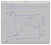
I try to simulate a smps with LTspice but get errors I can not remove.
what it does see pictures and the schematic to try yourself.
Also when using coils, like transformers how to put it the induction for it? it needs calculation first? I read about induction proportional to windings, so the outcome of a transformer calculation can not put in LTspice directly?
Can I not better use pspice 9.1
regards
kees
Attachments
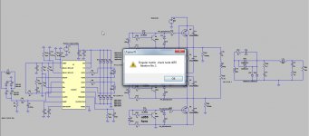
I have found after some research that I have to play with resistors and caps, but also change things to let it work, very high value resistors do work fine, ltspice likes gnd.
And I have did make a mistake with the full bridge, it is happely not real, then a big boom will end it, that is why i like ltspiceing.
regards
kees
And I have did make a mistake with the full bridge, it is happely not real, then a big boom will end it, that is why i like ltspiceing.
regards
kees
Please help to find model for IRF9510 .
TNX, Alex.
Available here
Vishay - MOSFETs - IRF9510, SiHF9510 - Power MOSFET
Hi.
.model 2sc2335 NPN(Is=3.971p Xti=3 Eg=1.11 Vaf=100 Bf=133.1 Ise=45.6p Ne=1.37
+ Ikf=2.635 Nk=.663 Xtb=1.5 Var=100 Br=3.227 Isc=9.551p Nc=1.437
+ Ikr=1.553 Rc=.1044 Cjc=2p Mjc=.3333 Vjc=.75 Fc=.5 Cje=5p
+ Mje=.3333 Vje=.75 Tr=2.655u Tf=1n Itf=1 Xtf=0 Vtf=10)
.model 2sc2335 NPN(Is=3.971p Xti=3 Eg=1.11 Vaf=100 Bf=133.1 Ise=45.6p Ne=1.37
+ Ikf=2.635 Nk=.663 Xtb=1.5 Var=100 Br=3.227 Isc=9.551p Nc=1.437
+ Ikr=1.553 Rc=.1044 Cjc=2p Mjc=.3333 Vjc=.75 Fc=.5 Cje=5p
+ Mje=.3333 Vje=.75 Tr=2.655u Tf=1n Itf=1 Xtf=0 Vtf=10)
Has anyone tried making a model for an IC like the MCP73831 or similar?
I haven't been able to find any model and perhaps it's not very easy to make a real one.
But perhaps a facsimile of this could be made. One that "emulates" the behavior, although it may not be a full model with all of the pure theory behind it.
I need this in a new design with a battery and more stuff, and as long as a model can make it act like the real thing, more or less, it would be sufficient.
Anyone?
By the way, is it possible with ltspice to make a "normal" simulation, with various parts and sources etc... , and then use that like a subcircuit to make it as if it was a single part/model? to use this in an other simulation, perhaps even more than once, in the same sim.
I made my own TDA2050 model which basically consists of making the device work in the kind of circuit you expect, then taking out all external parts used to prove the circuit and naming the nodes.
A bit of juggling and the model is added to LT's library to be called up as and when.
Is that what you mean ?
A bit of juggling and the model is added to LT's library to be called up as and when.
Is that what you mean ?
Attachments

That's exactly what I was thinking.
If we can make up a normal simulation with a bunch of parts and turn that into a model by itself to include as is in other sims, then it should be somewhat feasible to emulate those types of parts like those battery chargers.
I was just looking at this earlier, the innards of that MCP7381 or similar, should give enough details about its internals to make up something that works kinda like the real one.
At least this isn't a microcontroller with software that can't be simulated by analog spice.
I was about to attempt putting one together, but there are some details that are rather blurry and I'm not sure how to handle those.
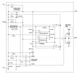
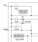
I attached the internal schematics of that 73831/2. One part I'm not sure how to handle is that CA/VA stuff, that is triggered by the termination/charge stage.
Most of those opamps look to me like schmitt trigger comparators, and those CA/VA that command those mosfets I'm not exactly sure. Maybe just comparators, but what about that extra input???
This should be interesting. I've been wondering for quite some time if we could put a full circuit into its own model. I guess we can do that. So I want to attempt this.
If we can make up a normal simulation with a bunch of parts and turn that into a model by itself to include as is in other sims, then it should be somewhat feasible to emulate those types of parts like those battery chargers.
I was just looking at this earlier, the innards of that MCP7381 or similar, should give enough details about its internals to make up something that works kinda like the real one.
At least this isn't a microcontroller with software that can't be simulated by analog spice.
I was about to attempt putting one together, but there are some details that are rather blurry and I'm not sure how to handle those.
I attached the internal schematics of that 73831/2. One part I'm not sure how to handle is that CA/VA stuff, that is triggered by the termination/charge stage.
Most of those opamps look to me like schmitt trigger comparators, and those CA/VA that command those mosfets I'm not exactly sure. Maybe just comparators, but what about that extra input???
This should be interesting. I've been wondering for quite some time if we could put a full circuit into its own model. I guess we can do that. So I want to attempt this.
Attachments
You've certainly got your work cut out with something like that but it could be doable.
CA/VA could be some kind of comparator with an enable/disable input or strobe (like the LM311) that the termination and charge comparators are able to override. Must be something in the standard parts library similar to that.
CA/VA could be some kind of comparator with an enable/disable input or strobe (like the LM311) that the termination and charge comparators are able to override. Must be something in the standard parts library similar to that.
You've certainly got your work cut out with something like that but it could be doable.
Well, since I need to simulate something using that IC, I need it, so I'm trying to do this. And if it works, I'm sure others can benefit from it.
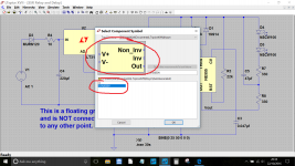
The lm311 is in the library, so I put that in those spots, and I figured the no-name buffer thingy that follows and commands the output mosfets for the stat signal must be something somewhat similar, so I used the behavioral buffer, non inverting (I hope) from the library.CA/VA could be some kind of comparator with an enable/disable input or strobe (like the LM311) that the termination and charge comparators are able to override. Must be something in the standard parts library similar to that.
Not sure how this will work, but it's a start.
I used ordinary mosfets from the library that I kindof hijacked to suit the purpose, but they're giving me an issue by not allowing editing. When I try editing, it says the symbol has been programmed to be not editable. I looked in the subckt and asy and can't figure out what in there would make it not editable.
I'm attaching a snapshot of what I've done so far, but one piece is missing: the direction control block on the top mosfet (attached). I don't know what could be in there.
At least I figured the reference generator would be a simple dc voltage source, but that block I have no idea what to make of it.
Attachments
By the way, don't mind those extra little things such as that voltage source on the left and those things on the bottom right. I need to test this to make it work, so it needs power and those things at the bottom are to test the stat output with a led and that resistor and big cap is what I though could fake a battery that would charge slowly (tweaking the R/C values).
I'm having an issue with those mosfet models that I tried to hijack from the library. Not only I can't make this work, but the resulting circuit would be difficult to share, so models would be better if they were embedded in the asc file.
Are there usable mosfet models that would be better to use for this?
Are there usable mosfet models that would be better to use for this?
Could it be some kind of bi-directional FET assembly like a solid state relay ? Two N channel FET's back to back and in series.
I think there are some logic level FET's in the library that have a very low Rds. Maybe rig up a little sim to test them all and see what Vgs they need and what the losses are.
Although you need the ground symbols in place to test the circuit, once its all done and ready to be made into a model you need to remove them. The grounds are then added externally when the model is used in its intended circuit.
Could it be some kind of bi-directional FET assembly like a solid state relay ? Two N channel FET's back to back and in series.
If that was the case, wouldn't they draw all of this, with all the mosfets?
All I see is that rectangular box that says "direction control", with the 3 connections to that mosfet below.
If more mosfets were involved, I would think those would be drawn as well.
But what do I know?
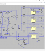
Not sure how to do that yet. But I switched to the most basic mosfets from the library, for which I have no idea about their specs, and since those don't have the schottky diodes, I added them separately, from those in the library.I think there are some logic level FET's in the library that have a very low Rds. Maybe rig up a little sim to test them all and see what Vgs they need and what the losses are.
So this should make the whole thing, so far, sharable as is, with all the models coming only from the library.
But not sure if it'll work at all yet.
Good point. And I'm practicing right now on a different model that doesn't have such elusive features in it: I'm doing this on a bryston discrete opamp (DOA33), for which there aren't any questions about its constituents.Although you need the ground symbols in place to test the circuit, once its all done and ready to be made into a model you need to remove them. The grounds are then added externally when the model is used in its intended circuit.
So far I tweaked the schematic to make it work, and just made a symbol for it. Now remains to be seen if I was able to link those 2 things up properly (.asc & .sym). But it seems, so far, that it's coming together.
However I'm not sure how to make that MCP73831 to work yet.
I'll attach what I did so far here. Since it's supposed to be all from library, it should "work" out of the box with only the asc file. But I was unable to get any results yet, there remain too many questions and configurations to make, such as the schmitt triggers, and perhaps that output buffer, and not sure if the lm311 will do the job requested.
Attachments
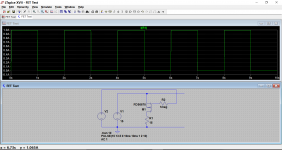
Something like this for the FET's. In simulation it doesn't actually matter if you pull 10 amps through a 100ma device. Its not going to burn a hole in the screen.
This shows a P channel FET switching 15 volts into 15 ohms, so we should see 1 amp flowing. The device here seems to work with 1.5Vgs. You might find an even better one. For N channel FET's just put a minus in front of all the voltages.
I'll have a look at your .asc later.
(just a thought, the FET I used may not be in the LT IV library... this is LT XVII)
Attachments

Something like this for the FET's. In simulation it doesn't actually matter if you pull 10 amps through a 100ma device. Its not going to burn a hole in the screen.
Of course, and as long as the result behaves more or less like intended in the datasheet, we're in business.
I'm not sure my idea to use an R/C instead of a battery will work as is to simulate a charging battery...
(just a thought, the FET I used may not be in the LT IV library... this is LT XVII)
Unfortunately I can't have the newest ltspice, as they have not made the mac version. And I have the feeling, once more, that we (the mac users) are being let down as usual.
But no matter, it should work fine with the version I'm still forced to use.
I guess using the library generic mosfets may not be quite suitable, but if we find models that work, let's go for it. The models can be embedded in the asc file, for easy sharing and make it work out of the box.
The model I am more likely to use later in my other simulations is the MCP73832, and the only difference I can see with the 831 is the single mosfet on the stat output instead of the 2. So making the 832 should be easy, as to simply delete the extra mosfet.
Well the FET asc did run OK in my copy of LT IV so the model is there (in Windows anyway) .
I had a quick look at your file... it wont be easy I suspect. The LT1011 comparator might be worth a look as it has a strobe input that is active when pulled down to ground via a suitable resistor (not a direct connection).
I had a quick look at your file... it wont be easy I suspect. The LT1011 comparator might be worth a look as it has a strobe input that is active when pulled down to ground via a suitable resistor (not a direct connection).
- Home
- Design & Build
- Software Tools
- Spice simulation