Member
Joined 2009
Paid Member

I reversed the tube in mine in pioneer sx3700
input selector > 6922 tube pre Av 10 > 250k volume pot > opa2134 tone controls , sx 3700 amp av 10
input selector > 6922 tube pre Av 10 > 250k volume pot > opa2134 tone controls , sx 3700 amp av 10
Thanks Gareth,
Now I understand; looks like Q4 sits on top of Q7 and same goes for Q13 with Q9
BR
Eric
Now I understand; looks like Q4 sits on top of Q7 and same goes for Q13 with Q9
BR
Eric
Member
Joined 2009
Paid Member
I reversed the tube in mine in pioneer sx3700
input selector > 6922 tube pre Av 10 > 250k volume pot > opa2134 tone controls , sx 3700 amp av 10
You took a good approach. You used the tube as a gain stage (I don't need or want any gain in my pre-amp except for phono) and likely this was a common cathode gain amplifier with high output impedance so you needed a high impedance volume pot. Which then needs a butter after it which you did with the OPA2134. Very nice. In my approach I get all the gain from the power amp, the pre-amp needs no gain so I used a tube as a cathode follower to buffer a lower impedance, 10k, volume pot. Different tradeoffs involved.
looks like Q4 sits on top of Q7 and same goes for Q13 with Q9
Yes, that's correct. The BD139's are sandwiched between the pcb underside and the power devices on the heatsink. I copied this approach from Hugh, who uses it on a number of his amplifiers. There are some tricks to assembly you need to follow though. First you bend the legs of the BD139 devices at their 'shoulders' then you insert the legs through the board from underneath and bolt the transistors through the pcb to ensure alignment of the mounting holes before you solder the leads. Then you bend the leads of the power devices at their 'shoulders' and insert the legs through the board from underneath. Then you bolt the whole assembly to the heatsink to ensure not only that the mounting holes are aligned but also that the power devices are at the correct distance from the board and that they are flat/parallel to the board. Then you solder the leads of the power devices.
The one BD139 is the Vbe multiplier so it should be in good thermal contact with the power device. I have used thermal pads in the past, this time I put some thermal grease on the BD139 device before I installed the power device. The other BD139 is the driver for the opto-isolator and it could be mounted on top of the pcb but at the time I did the layout I decided to stick it underneath so as to be useful as a 'spacer' for one of the power devices, making the mechanical stack-up symmetrical. This device does dissipate heat, few hundred mW actually, but it's temperature will be 'forced' by the power device it is in contact with and again, I used thermal grease between them.
They don't. It's PTC effect of the tungsten filament that gives the protection that a pair of secondary resistors cannot achieve.Too late, the damage has already been done in discharging the smoothing capacitors through the faulty wiring.
I guess I've been lucky as these 10R power resistors and DVM method has saved all my amps from any blown components now after a dozen amps. With 35v rails the most I have seen when an output is pegged to the rail is 25v or 2.5amps. So far this has not been enough to kill an OPS if I switch off within 10seconds. I have only lost MOSFETs on Circlotron due to thermal runaway not set right when I remove the 10R. That happens in like 6 seconds.
Very tidy build, Gareth!
You pay quite a compliment on my BD139/output layout, thank you!
Absolutely correct that you have to take care to bend the leads at the precise point to ensure proper device alignment. I don't bother with thermal paste; it seems to work just fine simply with close proximity; not mica or grease at all.
Hugh
Member
Joined 2009
Paid Member
Well after years of wanting to have some thermal grease I bought a little syringe of it from eBay a year ago and have been itching to use a little - of course it may be fake, but if it is cheap Mayonnaise I'm sure it will still add something good to the process !
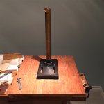
I'm also starting to assemble a drill press, as needed for the box. I found one in the weekend sales, thanks to a tipoff from Pronk.
I'm also starting to assemble a drill press, as needed for the box. I found one in the weekend sales, thanks to a tipoff from Pronk.
Attachments
Last edited:
Member
Joined 2009
Paid Member
I powered up the power amp using the power supply I built and with some resistors in the rails (I have 10R, 20R and 200R power resistors on-hand). No smoke.
However, the bias current is too high, I'm measuring around 150mA per output pair. I'm measuring around 9mA through the VAS (was expecting closer to 8mA but that's OK for starters). When I short the Vbe multiplier to force bias to zero I measure zero idle current through the output power devices.
I have the Vbe multiplier potentiometer at maximum resistance which should equate to minimum bias. The collector-base resistor on the multiplier is 1k5, the base-emitter resistor string is 220R in series with a 200R potentiometer. It behaves as if I have insufficient adjustment range on my Vbe multiplier. If I can confirm this is the case then it's an easy fix.
Last edited:
Thanks Bigun, My design goal is to get a tube sound quality but also have the amp be dead quiet at low levels. Currently I can just barely hear amp noise with my ear pressed to the speaker. the other benefit is pot wiper noise is reduced 10db due to less amplification after the volume pot.
Member
Joined 2009
Paid Member
Do you find that you need dc for the valve heater or do you get away with ac in terms of low noise ?
I'm really hoping to get away with ac heating using an extra winding on the main toroid, but since this transformer also feeds the main power rails which are rectified there is a risk of the current charging pulses feeding noise through to the signal via the heater supply. I haven't tried it to see.
I'm really hoping to get away with ac heating using an extra winding on the main toroid, but since this transformer also feeds the main power rails which are rectified there is a risk of the current charging pulses feeding noise through to the signal via the heater supply. I haven't tried it to see.
I have used AC heaters for a few power amps with good success. This one most recently. http://www.diyaudio.com/forums/soli...erformance-yet-rather-simple-hybrid-more.html
Nice project you have going.
Evan
Nice project you have going.
Evan
The Vbe multiplier is just a shunt regulator.I powered up the power amp using the power supply I built and with some resistors in the rails (I have 10R, 20R and 200R power resistors on-hand). No smoke.
However, the bias current is too high, I'm measuring around 150mA per output pair. I'm measuring around 9mA through the VAS (was expecting closer to 8mA but that's OK for starters). When I short the Vbe multiplier to force bias to zero I measure zero idle current through the output power devices.
I have the Vbe multiplier potentiometer at maximum resistance which should equate to minimum bias. The collector-base resistor on the multiplier is 1k5, the base-emitter resistor string is 220R in series with a 200R potentiometer. It behaves as if I have insufficient adjustment range on my Vbe multiplier. If I can confirm this is the case then it's an easy fix.
The regulator's output voltage is Rupper/Rlower+1 * Vbe
You can calculate the minimum output voltage, when Rlower is at maximum
and calculate the maximum output voltage when Rlower is at it's minimum value.
eg Rupper =2k
Rlower = 330R (fixed) plus 1kVR
Max output = 2000/330+1*Vbe = 7.06*Vbe
Min output = 2000/(330+1k)+1 *Vbe = 2.5*Vbe
If those values don't suit, change some of the Rupper and Rfixed values.
Member
Joined 2009
Paid Member
The strange thing for me is that the values I used worked just fine in Spice - the potentiometer was set at 77R and so with a 200R physical potentiometer I expected to have sufficient range. In general, I find Spice simulations to be pretty accurate. I guess it's possible that there is a different issue.
Member
Joined 2009
Paid Member
Thanks for the formula...The Vbe multiplier is just a shunt regulator.
The regulator's output voltage is Rupper/Rlower+1 * Vbe
So I have Rupper = 1,500R, Rlower = 220 to 420
Max output = 1500/220 +1 = 7.8 Vbe
Min output = 1500/420 +1 = 4.5 Vbe
hmmmm, the minimum output seems borderline for double EF, would be better if it were closer to 3.5 Vbe. I'll probably try changing the ratio when I get back tonight.
Attachments
Member
Joined 2009
Paid Member
I actually bought mine 20yrs ago at an electronics store in Berkeley. I think it was $5 but it's the same one for $0.99 from China. How does it make sense to be able to buy a box of 100 trimpots for $5 including handy divider case and free shipping?
100PCS/Box RM065 Variable Resistor Horizontal Trimpot Potentiometer Assortment Kit Free Shipping CGKCH164-in Potentiometers from Electronic Components & Supplies on Aliexpress.com | Alibaba Group
100PCS/Box RM065 Variable Resistor Horizontal Trimpot Potentiometer Assortment Kit Free Shipping CGKCH164-in Potentiometers from Electronic Components & Supplies on Aliexpress.com | Alibaba Group
Gareth, with this topology (2EF BJT) I use a 1k across B-C and that same 220R + 200VR across B-E. So replace the 1k5 with a 1k and you should be fine.
Member
Joined 2009
Paid Member
- Status
- Not open for further replies.
- Home
- Amplifiers
- Solid State
- TGM 1i - an integrated hybrid amp inspired by Hugh Dean