I have set up an interesting compensation on the SAKSA which is not used much; lag shunt to ground, and phase lead to the fb node. I found that it sounded better than the usual lag comp I use, and in fact I find the compensation more influences the sound quality than the topology... but I might be quite wrong after all. I am a pragmatist!
Hugh
Like my modification on Apex's FX8 and FX11?
Member
Joined 2009
Paid Member
Hugh,Damir,
I go where I can get good sound; I am not particularly fixed on one system. In fact the Maya uses VFA too! I have set up an interesting compensation on the SAKSA which is not used much; lag shunt to ground, and phase lead to the fb node. I found that it sounded better than the usual lag comp I use, and in fact I find the compensation more influences the sound quality than the topology... but I might be quite wrong after all. I am a pragmatist!
Hugh
I understand you perfectly, I am not fixed to one technology eider.
Next I will transform my CFA to VFA by adding a buffer to the low impedance FB input( I mean real amp not only simulated as I showed that already).
BR Damir
Bigun,
Only for ageing audiophiles - it is the SUPER AKSA but I am not so averse to your lascivious appelation.....
Bimo,
I have not seen your method but I would not be surprised - we seem to think alike!
Damir,
I am convinced your new VFA will sound excellent!
HD
Only for ageing audiophiles - it is the SUPER AKSA but I am not so averse to your lascivious appelation.....
Bimo,
I have not seen your method but I would not be surprised - we seem to think alike!
Damir,
I am convinced your new VFA will sound excellent!
HD
Last edited:
Member
Joined 2009
Paid Member


Member
Joined 2009
Paid Member
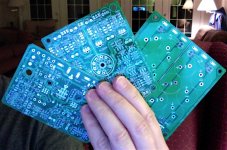
My matched transistors arrived from Hugh today. He included an unused pair of original AKSA-55 PCB's - I had goodbumps holding these things 😀
My foray into this amplifier building hobby started when I attempted to clone this AKSA-55 amp, driven on by rapturous comments posted by Carlos the Destroyer - all those years ago !
My foray into this amplifier building hobby started when I attempted to clone this AKSA-55 amp, driven on by rapturous comments posted by Carlos the Destroyer - all those years ago !
Member
Joined 2009
Paid Member
What about this ?
I'm using a single power transformer - not enough space for dual trafo's - so I have to decide on the grounding arrangement. I've ordered an Avel Lindberg power trafo with 35Vac secondary windings.
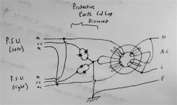
With a true dual trafo arragement (described as the preferred approach by AKSA in original guidance to builders of the AKSA amplifier) the left and right channels would be completely separated inside the chassis except where their ground connections, which are also connected to the centre-taps of the secondary of each trafo, are connected to the safety earth through a ground-loop-disconnect network of two-parallel-reverse-connected diodes. Of course their grounds can also be connected at the source via the RCA connecting cables - which is why there is a 'ground lift' resistor on the input to the AKSA amplifier.
With only one trafo I have only one centre tap of the secondary of the trafo. On first thought, this would mean the grounds of the two channels must be common at that point. Not one to be happy with such a compromise I am thinking I can separate the grounds of the two channels with diode networks and achieve the same degree of separation as when using dual trafo's. The centre tap does provide a stable low impedance 'anchor' for the power supply ground to prevent asymmetric low-level d.c. current flow in the circuitry from dragging the power rails.
The sketch says it all (except I should have shown some 10R resistors in parallel with the diodes)
Remember, there is normally no current flow to the centre tap of the trafo - ideally all the return currents flow back through the power supply filter capacitors. Significant d.c. current flow through the centre tap of the trafo may indicate a fault condition whereby there is significant d.c. current flowing through the speaker.
I'm using a single power transformer - not enough space for dual trafo's - so I have to decide on the grounding arrangement. I've ordered an Avel Lindberg power trafo with 35Vac secondary windings.
With a true dual trafo arragement (described as the preferred approach by AKSA in original guidance to builders of the AKSA amplifier) the left and right channels would be completely separated inside the chassis except where their ground connections, which are also connected to the centre-taps of the secondary of each trafo, are connected to the safety earth through a ground-loop-disconnect network of two-parallel-reverse-connected diodes. Of course their grounds can also be connected at the source via the RCA connecting cables - which is why there is a 'ground lift' resistor on the input to the AKSA amplifier.
With only one trafo I have only one centre tap of the secondary of the trafo. On first thought, this would mean the grounds of the two channels must be common at that point. Not one to be happy with such a compromise I am thinking I can separate the grounds of the two channels with diode networks and achieve the same degree of separation as when using dual trafo's. The centre tap does provide a stable low impedance 'anchor' for the power supply ground to prevent asymmetric low-level d.c. current flow in the circuitry from dragging the power rails.
The sketch says it all (except I should have shown some 10R resistors in parallel with the diodes)
Remember, there is normally no current flow to the centre tap of the trafo - ideally all the return currents flow back through the power supply filter capacitors. Significant d.c. current flow through the centre tap of the trafo may indicate a fault condition whereby there is significant d.c. current flowing through the speaker.
Attachments
Last edited:
Bigun,
Not sure if this helpful but take a look at Power Supply for Power Amplifiers. One transformer is shared by two channels with good isolation between the two channels.
Frank
Not sure if this helpful but take a look at Power Supply for Power Amplifiers. One transformer is shared by two channels with good isolation between the two channels.
Frank
I'm using a single power transformer - not enough space for dual trafo's - so I have to decide on the grounding arrangement. I've ordered an Avel Lindberg power trafo with 35Vac secondary windings.
With a true dual trafo arragement (described as the preferred approach by AKSA in original guidance to builders of the AKSA amplifier) the left and right channels would be completely separated inside the chassis except where their ground connections, which are also connected to the centre-taps of the secondary of each trafo, are connected to the safety earth through a ground-loop-disconnect network of two-parallel-reverse-connected diodes. Of course their grounds can also be connected at the source via the RCA connecting cables - which is why there is a 'ground lift' resistor on the input to the AKSA amplifier.
With only one trafo I have only one centre tap of the secondary of the trafo. On first thought, this would mean the grounds of the two channels must be common at that point. Not one to be happy with such a compromise I am thinking I can separate the grounds of the two channels with diode networks and achieve the same degree of separation as when using dual trafo's. The centre tap does provide a stable low impedance 'anchor' for the power supply ground to prevent asymmetric low-level d.c. current flow in the circuitry from dragging the power rails.
The sketch says it all (except I should have shown some 10R resistors in parallel with the diodes)
Remember, there is normally no current flow to the centre tap of the trafo - ideally all the return currents flow back through the power supply filter capacitors. Significant d.c. current flow through the centre tap of the trafo may indicate a fault condition whereby there is significant d.c. current flowing through the speaker.
I don't think that diode pair in each centre tap will work.I'm using a single power transformer - not enough space for dual trafo's - so I have to decide on the grounding arrangement. I've ordered an Avel Lindberg power trafo with 35Vac secondary windings.
With a true dual trafo arragement (described as the preferred approach by AKSA in original guidance to builders of the AKSA amplifier) the left and right channels would be completely separated inside the chassis except where their ground connections, which are also connected to the centre-taps of the secondary of each trafo, are connected to the safety earth through a ground-loop-disconnect network of two-parallel-reverse-connected diodes. Of course their grounds can also be connected at the source via the RCA connecting cables - which is why there is a 'ground lift' resistor on the input to the AKSA amplifier.
With only one trafo I have only one centre tap of the secondary of the trafo. On first thought, this would mean the grounds of the two channels must be common at that point. Not one to be happy with such a compromise I am thinking I can separate the grounds of the two channels with diode networks and achieve the same degree of separation as when using dual trafo's. The centre tap does provide a stable low impedance 'anchor' for the power supply ground to prevent asymmetric low-level d.c. current flow in the circuitry from dragging the power rails.
The sketch says it all (except I should have shown some 10R resistors in parallel with the diodes)
Remember, there is normally no current flow to the centre tap of the trafo - ideally all the return currents flow back through the power supply filter capacitors. Significant d.c. current flow through the centre tap of the trafo may indicate a fault condition whereby there is significant d.c. current flowing through the speaker.
The charging currents pass from the secondary through the diode to the rectifier first in one direction then in the other.
Member
Joined 2009
Paid Member
Hi Frank, yes, I'm doing something like this, but wondering if I can get some separation between the ground connections. If not then so be it, it will be the place where the grounds come together.Not sure if this helpful but take a look at
What happens if the centre-tap were not connected and left floating ? - the rail caps would still charge up would they not ?The charging currents pass from the secondary through the diode to the rectifier first in one direction then in the other.
If the centre-tap were separated from the common point of the rail capacitors the charging pulses would flow through the rail caps to the opposite rail and back to the other side of the transformer secondary would they not ?
First parts order now placed with Digikey.
Attachments

AKASA
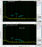
Compensation is one of the tricks 😀 (proof bellow) But there is a few more.
There is a lot of work involved to discover them all (current mirror balance, boostrap tricks, etc). Many, many hours in the lab and a lot of coffee too...
Boyz from Marantz not without the reason are putting the small caps in between GND and rest of the circuit.
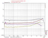
What I found a bit difficuld is to keep the harmonics ratio the same threw all audio band (the B-mos pic), especially at the top octave.
Now it will be a bit wierd but, sometimes it is good to make a brilliant amplifier and than make it worse in a good way 😀
Compensation is one of the tricks 😀 (proof bellow) But there is a few more.
There is a lot of work involved to discover them all (current mirror balance, boostrap tricks, etc). Many, many hours in the lab and a lot of coffee too...
Boyz from Marantz not without the reason are putting the small caps in between GND and rest of the circuit.
What I found a bit difficuld is to keep the harmonics ratio the same threw all audio band (the B-mos pic), especially at the top octave.
Now it will be a bit wierd but, sometimes it is good to make a brilliant amplifier and than make it worse in a good way 😀
Attachments
Member
Joined 2009
Paid Member
Now it will be a bit wierd but, sometimes it is good to make a brilliant amplifier and than make it worse in a good way 😀
I like your way of thinking 😉
Well, bad of 'loot' from Digikey today, spent enough to qualify for free shipping!
Attachments

Member
Joined 2009
Paid Member
Some drilling and filing and I have the back-panel populated. There's a pair of line-input RCA's and a pair for phono with a ground terminal for turntables with separate ground straps - it will be connected to the casework.
With the casework all anodized I'm worried that I won't have a good safety earth connection to all the pieces - will have to check with a multi-meter once it's all assembled.
PCB's are now en-route to my house.
With the casework all anodized I'm worried that I won't have a good safety earth connection to all the pieces - will have to check with a multi-meter once it's all assembled.
PCB's are now en-route to my house.
Attachments
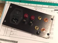
With a screw on anodized rear panel, I recommend at least one extra Earthing wire to a side panel and/or to the floor panel. i.e. two or three wires from IEC Earth to the chassis.
Member
Joined 2009
Paid Member
...thanks man !Very nice work Bigun !
Next up: I tried to do some more drilling of the baseplate, needs carefully aligned supports for the trafo, pcb's and for some air flow. I marked all the holes out carefully and used a centre punch. But my hand-held power drill just wouldn't hold a stable path through the metal. It's junk, the baseplate is a mess and simply not worthy of this project. AAARRRRRRRGH !
I've never been happy with my workmanship using a hand held power drill - over the years this approach has made chassis work a bloody pain in the ar5e. I'm done with this torture, I'm going to buy a bloody drill press so I can do the job properly.
Now that I screwed up the base plate I'm short a piece of black anodized aluminium. I'm thinking I'll use the top plate for the base. I can substitute a piece of clear acrylic for the top plate and get a nice view of my amp for years to come.
Attachments

Last edited:
Member
Joined 2009
Paid Member
Postman visited the house today...
I like to see this distinctive circle of 9 pins on the board 😉
Have a nice build, Gareth

Looking forward to seeing the tests 😎
- Status
- Not open for further replies.
- Home
- Amplifiers
- Solid State
- TGM 1i - an integrated hybrid amp inspired by Hugh Dean