Member
Joined 2009
Paid Member
Very interesting project😎It's gonna be slow progress as I have a lot of other stuff eating up my time, but I'm going to sort out all the parts into three bins today, one bin for each board (psu, preamp, poweramp). I've got some heatsinks tapped and ready for the power amp.
Member
Joined 2009
Paid Member
Heater supply
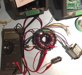
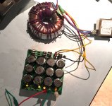
The heater of the pre-amp tube needs a 6.3Vac heater supply which I am tempted to get by adding a winding to the power transformer. Being a toroidal transformer it's relatively easy to wind some extra wire over it.
I put 4 turns of wire on the transformer and found that unloaded I get 0.878Vac. Using this I can calculate that I'll need about 29 turns. I added 29 turns of insulated multi-stranded wire (cus this is what I had on hand) around the transformer.
Unloaded it gives me 6.45Vac. Then loaded up on a tube with 300mA heater it drops nicely to 6.33Vac. Looks like it could be a viable approach. Of course it'll pick up rectifier noise from the +/- supplies so I'll think about a capacitor or two later on to draw this off to ground.
Attachments

Member
Joined 2009
Paid Member
Thanks !
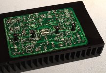
Standard stuff on the pcb. I've never ordered the extra thick, never crossed my mind to do so. Maybe a good idea though if you were planning to run continuously high currents or just wanted to halve the thermal and electrical resistance of the traces.
I'm not after really high power here, as you can see from the small transformer, rather I like to operate at the higher rail voltage because it gives me better headroom for peaks and a better operating point for some of the devices, including the triode.
Member
Joined 2009
Paid Member
Member
Joined 2009
Paid Member
PSU powere-up
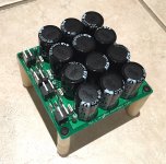
I tested out the PSU - just basic power it up and see if it blows up or produces the predicated voltage.
Well it nearly blew up. I've done this before so not sure why I made the same mistake again, but I plugged the trafo into the wrong pins on the board - swapping around the centre tap with one end of the secondary. If you trace out the circuit you'll see that this turns it into a voltage doubler so within milli-seconds my 63V caps had 80V across them, and climbing...... power-off fast ! discharge with a 2k2 resistor (it got warm) and then switch wires around and all is good again. Got +/- 54V unloaded at the output of the power supply.
Attachments
Beautiful PCB, look like a dual mono on a single PCB.
Cool, so far 1 PCB out of 3 is working...nice ;-)
I'm a little late to the party so maybe you already mentionned this..what do you recommand as far as transformer for the power amp section ? Would a 250VA, +/- 30Vac per channel sufficient ?
Thanks,
Eric
Cool, so far 1 PCB out of 3 is working...nice ;-)
I'm a little late to the party so maybe you already mentionned this..what do you recommand as far as transformer for the power amp section ? Would a 250VA, +/- 30Vac per channel sufficient ?
Thanks,
Eric
Last edited:
Member
Joined 2009
Paid Member
I went with dual-mono all the way through for the pcb's which suggests using two power transformers. I don't have the space so I'm using just one but if you had the coin and the chassis space then two separate power transformers is the prefferred approach.
Others will disagree but for size of trafo I'd say it depends on what you are trying to achieve in terms of continuous use output power. You want +/- 35Vac from the secondary which will give the design-value of around +/-50Vdc. I expect things would also work with +/-30Vac and +/-42vdc with some thought.
Others will disagree but for size of trafo I'd say it depends on what you are trying to achieve in terms of continuous use output power. You want +/- 35Vac from the secondary which will give the design-value of around +/-50Vdc. I expect things would also work with +/-30Vac and +/-42vdc with some thought.
Great photos and progress notes.
I'm with you Bigun - its difficult to justify two transformers, especially when space is so tight in most enclosures.
A single, larger transformer will probably have better regulation than two smaller transformers, which is also something worth considering.
I once built a fully dual mono amp and have never bothered since. I'd say the improvements were marginal at best.
Great photos and progress notes.
I'm with you Bigun - its difficult to justify two transformers, especially when space is so tight in most enclosures.
A single, larger transformer will probably have better regulation than two smaller transformers, which is also something worth considering.
I once built a fully dual mono amp and have never bothered since. I'd say the improvements were marginal at best.
+ 1
ALL my power amp uses a single larger power transformer. The only time I've used dual mono was for my VSSA (based on some recommendation). Once the VSSA was completed my ears couldn't tell there was any improvement over a single PSU. Since then dual mono is history for me.
BR,
Eric
Member
Joined 2009
Paid Member
You know, the quality of the supply and decoupling between channels becomes more critical as the PSRR of the amplifier falls. Single ended Class A amplifiers without feedback can be the most sensitive. The AKSA amplifier does have some supply sensitivity - the interaction of music waveforms on the +ve power rail with the Class A front-end is important for the signature sound of this topology and noise on the -ve power rail can ingress at the single ended Class A VAS. Amplifiers with very high PSRR interact less with the power supply, although most Class AB amps have to accept some droop in the rails when powerful LF bass notes are in play.
fyi - I've incorporated an optional 'upgrade' to the VAS on the pcb which would greatly enhance the PSRR (through higher feedback factor for lower distortion) but I'm not sure yet if I want to deviate from the original AKSA design.
The pre-amp has an on-board shunt regulator so it should be clean if the grounds can be kept clean.
Last edited:
A second transformer is a real brute force solution to the problem (assuming there is a problem) and if the PSR of the basic amp is that bad then channel interaction is probably not the biggest issue.
In terms of the power amp, the PSRR of the +ve rail is greatly improved by giving the LTP a proper current source. Simply moving R10 would make a difference. The -ve rail can be improved with an RC filter between the driver and VAS; 10R and 1000uF would do nicely. Or alternatively cascode the input pair and move the Cdom connection.
But of course we all know all these tricks. My point is that if we are contemplating something as drastic as a second transformer, why not look to address the underlying problem?
Very interested in your VAS upgrade, care to share :-D
Member
Joined 2009
Paid Member
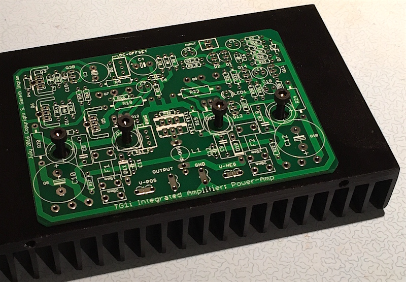
Power Amplifier
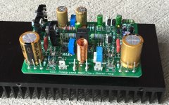
This forum thrives on power amps, so I've started assembling one. Found one of the resistor footprints was undersized (my fault) and the assembly is a bit fiddly with the mechanical stack-up but it seems to have all gone together. I'm missing the catch-diode, my junk box diodes were too fat but these can be added later.
My bench top regulated power supply doesn't reach +/-50V so no safe current limited option. I will use the power supply board made for the amplifier and put some power resistors in series with the rails for the first power-up - excess current draw will pull the rail voltage down and hopefully avoid disaster if the bias is wrong or some other mistake.
Attachments
Member
Joined 2009
Paid Member

Beautiful work !!
Do yourself a favor and quickly built a power cord with a light bulb (120Vac, 60W) inserted in series on the live side, it could prevent a disaster.
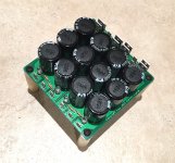
p.s. Where are the tabs of transistors Q7, Q9 all we see is the legs that are soldered...
BR
Eric
Do yourself a favor and quickly built a power cord with a light bulb (120Vac, 60W) inserted in series on the live side, it could prevent a disaster.
p.s. Where are the tabs of transistors Q7, Q9 all we see is the legs that are soldered...
BR
Eric
Last edited:
The power resistors do same job as light bulb but work on DC rails. A voltmeter across the power resistor is useful to give current as well. Anything above 1A (10V on a 10R) on startup is a sign to quickly shutoff power to transformer and debug before anything fries.

They don't. It's PTC effect of the tungsten filament that gives the protection that a pair of secondary resistors cannot achieve.The power resistors do same job as light bulb but work on DC rails.
Too late, the damage has already been done in discharging the smoothing capacitors through the faulty wiring.A voltmeter across the power resistor is useful to give current as well. Anything above 1A (10V on a 10R) on startup is a sign to quickly shutoff power to transformer and debug before anything fries.
Member
Joined 2009
Paid Member
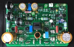
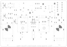
Where are the tabs of transistors Q7, Q9 all we see is the legs that are soldered...
Not sure if the attached makes it clearer - the dashed lines are the outlines of the power devices, this image shows more or less what is mounted under the board.
Attachments
- Status
- Not open for further replies.
- Home
- Amplifiers
- Solid State
- TGM 1i - an integrated hybrid amp inspired by Hugh Dean