Hi all.
What are you using for output stage?
I have build a tda1541 before and then used a lampizator 6n2p stage...
Any good easy discrete stage?
Best Regards //Daniel
Hi Daniel,
Have you considered using CEN/SEN? All you need to add is a 2mA constant current source for the current offset of the TDA1541A, the biggest challenge is getting the voltage on the outputs stable enough to maintain 0V DC, otherwise distortion will result (clearly audible, even at +- 7mV). This is something I have to work on further in my own system.
Ryan
Transformer IV
Since we are on the topic of output stages, i've attached a circuit that uses a Lundahl LL1678 using 1:32 turns ratio option. It has a CCS for TDA1541A current offset, a source follower for the current gain after the transformer. THD simulates at 0.008%. No where near as low as the CEN/SEN though, maybe worth trying, I have not tried this circuit yet.
Since we are on the topic of output stages, i've attached a circuit that uses a Lundahl LL1678 using 1:32 turns ratio option. It has a CCS for TDA1541A current offset, a source follower for the current gain after the transformer. THD simulates at 0.008%. No where near as low as the CEN/SEN though, maybe worth trying, I have not tried this circuit yet.
Attachments

I would love to be able to build a valve (tube) but I hate the high voltage involved with these circuits, I know that its regarded as the best, but also valves do colour the sound as well to a curtain degree but I do like valves though I have a 6L6 valve amp and tube guitar amp, but is there any chance someone could suggest a transistor output something like Hdam for somebody like me with limited skills?
I would love to be able to build a valve (tube) but I hate the high voltage involved with these circuits, I know that its regarded as the best, but also valves do colour the sound as well to a curtain degree but I do like valves though I have a 6L6 valve amp and tube guitar amp, but is there any chance someone could suggest a transistor output something like Hdam for somebody like me with limited skills?
Valves dont have to bo coloured. It depends on what you build. Ryans suggestion for a cen/sen stage would be my second pick.
I would love to be able to build a valve (tube) but I hate the high voltage involved with these circuits, I know that its regarded as the best, but also valves do colour the sound as well to a curtain degree but I do like valves though I have a 6L6 valve amp and tube guitar amp, but is there any chance someone could suggest a transistor output something like Hdam for somebody like me with limited skills?
There is more than a few ways to do it.. not all need to be as high in voltage terms as you might think. 60V on the plate of 6922 will do fine if you bias it direct from the 1541A - no need for current injection to zero the output at the AOL/R (which in this case is both counter intuitive and counter productive in terms of the 'natural' unmolested balance between odd and even order harmonic distortion) - allow some margin for loading and you're done.
There are other tubes which set up near zero grid bias as well.
LH/S
Hi Ryanj,
Just received the pbc's and they are very impressive thank you so much for your efforts, I am looking forward to this build. 🙂
Just received the pbc's and they are very impressive thank you so much for your efforts, I am looking forward to this build. 🙂
Stability issue to look out for.
Hi Guys,
I've assembled another PCB today and ran into a stability issue.
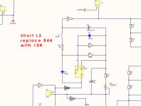
If you run into the same issue just remove and short the pads of L3 and replace R44 with 10R instead of 1R.
Sorry for the inconvenience, at least I ran into the problem first, and its an easy fix thankfully.
It's strange that this didn't show up before.
I'll update the schematics and include this mod.
Ryan
Hi Guys,
I've assembled another PCB today and ran into a stability issue.
If you run into the same issue just remove and short the pads of L3 and replace R44 with 10R instead of 1R.
Sorry for the inconvenience, at least I ran into the problem first, and its an easy fix thankfully.
It's strange that this didn't show up before.
I'll update the schematics and include this mod.
Ryan
Attachments
Hi Ryanj,
Just received the pbc's and they are very impressive thank you so much for your efforts, I am looking forward to this build. 🙂
Thanks Peterma,
Good luck with your build, did you decide on an IV stage yet?
Ryan
Hi Guys,
I've assembled another PCB today and ran into a stability issue.
Ryan,
Boards arrived yesterday - thank you very much.
Regarding the stability issue, how does it manifest itself? In other words, how does one know if one has a problem or not.
Thanks,
---Gary
Hi Gary,
Your welcome.
The first thing you will notice is very low current draw of about 10mA from the 26V supply, and as a result very low output voltages. Once I started probing around I found the output of V1 was oscillating at 6.2meg.
If you do get this problem, replace:
L3 with: WSC452710R00FEA -check footprint size with MSS1210-106KEB, as I havn't tried this yet, but looks like it will fit up fine.
R44 with: CRCW25120000Z0EG
L3 + R44 should equal around 10 ohms to keep the circuit at the correct DC operating points.
Good luck with your build Gary.
Ryan
The first thing you will notice is very low current draw of about 10mA from the 26V supply, and as a result very low output voltages. Once I started probing around I found the output of V1 was oscillating at 6.2meg.
If you do get this problem . . .
Ryan,
I wonder if the problem might also be solved by putting a small capacitor right at the output of V1 (LM317). The datasheet recommends at least 1uf from Vout to ground. The current schematic has a big capacitor (1500uf) but it's isolated by L3. Admittedly putting in the extra capacitor is harder since there isn't a convenient set of pads for that. Just thought I'd throw out an alternative that would let one keep the inductor in place.
---Gary
Hi Gary,
Thanks for the tip. A 1uF from V1 out to ground certainly did the trick. It also works the same with 1uF from V1 out to the negative of input supply.
At this point I just have to laugh at myself, heres me worried about noise from an LED and putting 1uF across it... LOL
Thanks for having faith in a total amature guys!
Ryan
Photo of mod.
Hi Guys,
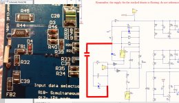
Just thought I'd upload this photo to show how to fix the oscillation issue if you come across it.
I used a 100nF (C3216C0G1H104K160AA) from V1 out to the negative of the 26V supply.
Has anyone started or finished their build?
Don't let this little issue stop you, i've had some good feedback from a well respected set of ears recently - "bloody incredible improvement in the dac's sound" was the phrase used. One thing to remember is that if there are any weak links in your system, it may very well reveal itself even more so once making this upgrade or any upgrade for that matter.
Hope it doesn't sound like im trying to sell anything, just really interested in what all the well tuned ears of DIYer think...
On another note... the Clone Note by Uriah Daley was put into my system just recently, and I must say, its as if there is no attenuator between DAC and power amp (CEN ---> F5) at all, a very welcome improvement.
Ryan
Hi Guys,
Just thought I'd upload this photo to show how to fix the oscillation issue if you come across it.
I used a 100nF (C3216C0G1H104K160AA) from V1 out to the negative of the 26V supply.
Has anyone started or finished their build?
Don't let this little issue stop you, i've had some good feedback from a well respected set of ears recently - "bloody incredible improvement in the dac's sound" was the phrase used. One thing to remember is that if there are any weak links in your system, it may very well reveal itself even more so once making this upgrade or any upgrade for that matter.
Hope it doesn't sound like im trying to sell anything, just really interested in what all the well tuned ears of DIYer think...
On another note... the Clone Note by Uriah Daley was put into my system just recently, and I must say, its as if there is no attenuator between DAC and power amp (CEN ---> F5) at all, a very welcome improvement.
Ryan
Attachments
Hard to get the 16ST226MD35750, I have tried everywhere, anybody got any ideas for alternative?
Hard to get the 16ST226MD35750, I have tried everywhere, anybody got any ideas for alternative?
I've been getting mine from Digikey.
Hard to get the 16ST226MD35750, I have tried everywhere, anybody got any ideas for alternative?
I can't get those from Mouser. Is it possible to use a X7R 22uf/16V?
BR //Daniel
I can't get those from Mouser. Is it possible to use a X7R 22uf/16V?
BR //Daniel
Wow !
I can't get those from Mouser. Is it possible to use a X7R 22uf/16V?
BR //Daniel
Hi Daniel,
I would probably not use an X7R in this position. The capacitor in this position is likely to make a substantial impact not only on sound quality but circuit performance. If I were to choose an alternative to the PMLCAP I would first try no cap in this position at all. With no cap in this position output impedance in the audio band doubles (3.6mohms without, and 1.8mohms with a 22uF).
Ryan
For those ordering from Mouser here's a project
* B2B-XH-A(LF)(SN): not part of the project BOM
** alternatives in Ryan's BOM is included, and thus one needs to remove one or the other.
Price incl. alternatives (without B2B-XH-A(LF)(SN)'s) ~ 30USD
- Home
- Source & Line
- Digital Line Level
- TDA1541A Diy Pcb - "Distinction-1541 v2"