the 220uF coupling capacitors are from the traditional 600ohms balanced interface.Hi Valery,
I noticed big 220u elco's on outputs. Is this necessary or can we bypass and go DC? Or maybe out good 1uF film cap bypass?
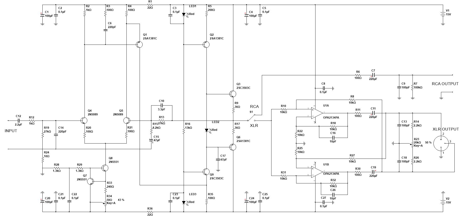
220uF and 600ohms gives an F-3dB of ~1.2Hz.
If you know you have a minimum load of 5k, then you can reduce the DC blocking capacitors to 33uF and even smaller if you have around 50k to 100k as the load.
As stated earlier, you only need one set of DC blocking capacitors in any connection.
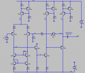
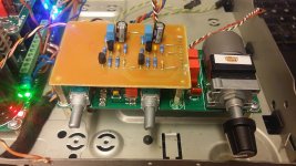
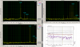
I have made yesterday a simple preamp. A bit similar to marantz PM7000 front end or the AD797 OPamp. The ADPreamp is very simple, performance is good to. It is dead quiet at idlle. I have measured it with 1k load and didn't blow up 😀. The modulated 3kHz 4kHz and 5kHz doesn't show any IMD products (only my crappy psu noise).
With two mosfets at the back or BD's could create a nice headamp.
I have shorted the NFB cap and the offset was about 5mV, so with a bit of the work it can be done a full DC coupled (I hope anyway).
Regards Pit
Very nice measurements Borys. Amazingly clean square waves.

Can you share PCB file or PDF layout?
Thanks,
X
xrk971
I do not have PCB for it yet. I have made it in free air kind of setup. I will prepare board in next few days for it.
Regards
I do not have PCB for it yet. I have made it in free air kind of setup. I will prepare board in next few days for it.
Regards
Hi guys
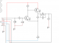
Here is my contribution; a simple discrete line stage that I've successfully incorporated into several projects as an input buffer, with modest gain to negate losses in the following balance/volume controls that feed the power amplifier section.
The output buffer as shown is required when driving relatively low value pots since the VAS needs to produce almost all the loop gain. Input transistor gm is very low due to the very heavy degeneration, making it trivial to compensate as a result.
The circuit is very conventional in almost every respect. It is fully AC coupled, which has the practical advantage that it can be powered from a single rail from the main amplifier without requiring additional transformer windings and separate power supplies. Turn on pop due to charging of the caps can be a problem unless you use some sort of speaker protection with turn on delay as I do.
I guess the only other real weakness is that PSR is not especially brilliant, particularly as supply ripple will couple into the CCS via C105 and then into the output node. Past versions I have used a discrete series regulator to filter the rail but the simple RC filter as shown also works well.
Attachments
Thank Mile
Tell me please, from experience which preamp topology adds more ''flawour'' to the sound ?
Regards
Peter
Folded cascode is my favorite topology, adds is inaudable for my ears.
Regards
Hello everyone
Small additional schema list
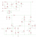
There in a long time in a French magazine appeared that little line preamplifier in class A. I had realized at the time and it really sounded good.
🙂
Interesting. Is the IC a 78xx voltage regulator IC used as a CCS?
Interesting. Is the IC a 78xx voltage regulator IC used as a CCS?
Attachments
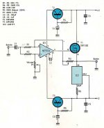
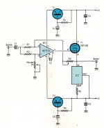
Here's a circuit I've played with using Bob Cordell's SPICE models. BC550 and 560 only. First stage input bias currents are NOT negligible so either AC couple it, or build a DC servo.
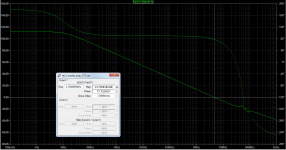
Bandwidth is 4.7 Megahertz at gain = 21X ((R13+R14)/R14) , therefore gain bandwidth product is 98 MHz (!).
Consider heatsinking the output stage.
Bandwidth is 4.7 Megahertz at gain = 21X ((R13+R14)/R14) , therefore gain bandwidth product is 98 MHz (!).
Consider heatsinking the output stage.
Attachments
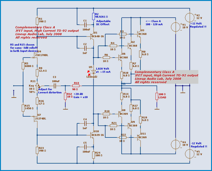
2000mA TO-92?!!
Why would anyone use a 2A device in a TO-92 package??
Looks like the heat wouldn't transfer very well through all that plastic.
No fun?
Sometimes even I like the smell of "magic smoke" emanating from a component going up in flames.😱
Sure beats cigarettes!🙂
Sometimes even I like the smell of "magic smoke" emanating from a component going up in flames.😱
Sure beats cigarettes!🙂
Nice layout!
Can you please post the Gerbers?
Thanks.
Not tested or checked. 😀
Attachments
Not tested or checked. 😀
Thank you!
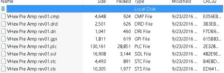
Just looking over your Gerbers, I don't understand them.
Can you convert them in Eagle to the standard format used by board manufacturers? The only one I recognize is the drill file.
GTL for top layer, GBL for bottom layer, GTS top mask, GBS bottom mask, etc.
Attachments
Last edited:
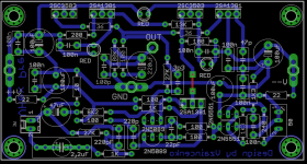
Today I gave a chance to another circuit. It is very basic and simple. Dead quiet and sounds really OK.
With my previous circuit from post 277 I have small problem on the new board. Free air design was working OK but after I made new board for it, preamp started to throw some small amplitude but MHz freq oscillations. I need a bit more time to sort it out.
With my previous circuit from post 277 I have small problem on the new board. Free air design was working OK but after I made new board for it, preamp started to throw some small amplitude but MHz freq oscillations. I need a bit more time to sort it out.
Attachments

Thank you!
Just looking over your Gerbers, I don't understand them.
Can you convert them in Eagle to the standard format used by board manufacturers? The only one I recognize is the drill file.
GTL for top layer, GBL for bottom layer, GTS top mask, GBS bottom mask, etc.
I use gerber247 cam from eagle and preview output file using gerbv.
- Home
- Source & Line
- Analog Line Level
- Transistor Preamp