I use gerber247 cam from eagle and preview output file using gerbv.
Okay, I figured out which file is for what.
For info, the Jrp27 fellow, started another thread. may be he got disgusted/confused with flurry of designs 🙂..
Oh, he got what he asked for in the very first page 🙄 ... the following 300 or so posts come from his stubborness 😀For info, the Jrp27 fellow, started another thread. may be he got disgusted/confused with flurry of designs 🙂..
Now we´ll have *another* 300 somewhere else 😛
Oh well 🙂
For info, the Jrp27 fellow, started another thread. may be he got disgusted/confused with flurry of designs 🙂..
Well not really...didn't get disgusted but confused...yes!
Didn't really mean to rack up 300 posts. I swear !
The thread turned into a great collection of preamp designs.
I agree ! A guy like me would need a year to make all of them 😀
My version of simple "blameless" pre-amp. Not tested!
Maybe it better to add DC Offset adjustment.
THD at 20kHz should be 0.002978%, sorry.
Hello. what is the forward voltage drop of the red led you are using? i have some red leds with 1.6V and other ones with 2V voltage drop and it makes difference to the output stage quiscent current.
this is your schematic : http://www.diyaudio.com/forums/atta...73478564-transistor-preamp-pre-amp-simple.pdf
Adjust your resistor to give the current you require.Hello. what is the forward voltage drop of the red led you are using? i have some red leds with 1.6V and other ones with 2V voltage drop and it makes difference to the output stage quiscent current.
this is your schematic : http://www.diyaudio.com/forums/atta...73478564-transistor-preamp-pre-amp-simple.pdf
Just don't use a high voltage LED, no blue and no white. They have more noise.
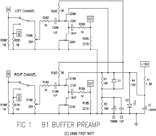
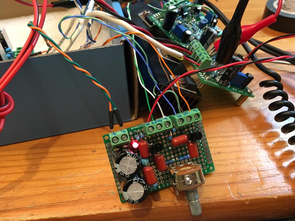
This thread has languished for a while. But last night I threw together a Pass B1 buffer preamp for the first time. Just two 2Sk170's in a clever single ended class A setup and I have what I think is one of the finest sounding preamps I have heard. The simplicity ensures low noise and this one is silent. It is so easy to make and requires no PCB. I did a Stereo P2P with pot and screw terminal blocks all on a standard 4cm x 6cm veroboard. It uses a single rail supply (nominally 18v) but since my headamp has 15v that's what I am using. If you have a quiet power source already, there is no need for the 10mF caps. I saved some real estate using 2.2mF caps and lower cost 1uF 230v film caps. I did match the JFETs for Idss for optimal performance.
Here is schematic from the B1 http://www.diyaudio.com/forums/pass-labs/124889-b1-buffer-preamp-418.html in case anyone does not remember what it looks like:
Here is my build being tested with my Juma BJT/MOSFET headamp
Anyhow, it sounds great and IMO, beats any op amp in simplicity and SQ if you only need a buffer to go from high to low impedance and have a volume pot in between. Because there is no DC current flow in the pot, it is silent as you change volume.
I am using a combo 10uF 50v MLCC cap bypassed with 1uF 230v film cap to save real estate and cost. Sounds fine to my ears but AndrewT did warn that an MLCC in such a spot with DC bias may distort. If you have room use a 10uF film cap (they will be same size as entire PCB and cost more than all the rest of the parts).
Highly recommend buffer preamp.
Last edited:
A source follower with current source, to be precise, made extra simple by JFETs being depletion mode.Just two 2Sk170's in a clever single ended class A setup
The original value of C2 is ridiculously oversized anyway. Yours still takes about 20 seconds for midpoint voltage to get anywhere near steady state, the original must take minutes. I have a little headphone amp using no more than a measly 10 µF for a rail splitter just like that - it is, admittedly, not exactly pure canned PSRR as evidenced by audible hum on an unregulated wall-wart. The value always struck me as ample, but I just ran a little sim, and -36 dB at 100 Hz doesn't sound that hot either, now does it? It's almost -80 dB for 15 mF.If you have a quiet power source already, there is no need for the 10mF caps. I saved some real estate using 2.2mF caps and lower cost 1uF 230v film caps.
With all that filtering going on, the B1 buffer must have phenomenal PSRR when wired up right - and it's not like the source follower circuit itself doesn't have any to begin with.
Hello. what is the forward voltage drop of the red led you are using? i have some red leds with 1.6V and other ones with 2V voltage drop and it makes difference to the output stage quiscent current.
this is your schematic : http://www.diyaudio.com/forums/atta...73478564-transistor-preamp-pre-amp-simple.pdf
I use Bob Cordell's model. It is about 1.6V to 1.8V.
You can use the output emitter resistors to adjust the output bias current/voltage.Hello. what is the forward voltage drop of the red led you are using? i have some red leds with 1.6V and other ones with 2V voltage drop and it makes difference to the output stage quiscent current.
this is your schematic : http://www.diyaudio.com/forums/atta...73478564-transistor-preamp-pre-amp-simple.pdf
Try with your low Vf LED and compare to the high Vf LED at the same output bias current.
On another thread, I wanted to know how to make a good simple preamp for driving a class A headphone amp. Juma of course, has another neat and simple solution:
http://www.diyaudio.com/forums/pass-labs/146310-bf862-preamp-35.html#post4426944
Gain adjusted via R3 (in reasonable range: from 100R for 17dB gain to 470R for 6dB gain).
Thanks, Juma!
http://www.diyaudio.com/forums/pass-labs/146310-bf862-preamp-35.html#post4426944
Gain adjusted via R3 (in reasonable range: from 100R for 17dB gain to 470R for 6dB gain).
Thanks, Juma!
Last edited:
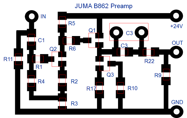
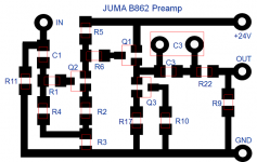
Juma BF862 Preamp Layout
Maybe something like this (about 35mm x 20mm):
This is purely eyeballed layout in PowerPoint graphics... 🙂
Maybe something like this (about 35mm x 20mm):
This is purely eyeballed layout in PowerPoint graphics... 🙂
Attachments
Last edited:
Q3 is placed the wrong way 😉
If you turn it 180 degrees and place R10 on the left from R17 - that'll be fine.
If you turn it 180 degrees and place R10 on the left from R17 - that'll be fine.
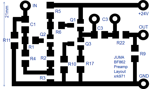
I read the spec sheet for BF862 and it says that S and D pins are interchangeable?
http://www.nxp.com/documents/data_sheet/BF862.pdf?
So does it matter, or maybe it sounds better with S & D pins in proper orientation?
Anyhow, I flipped Q3 to make it so:
http://www.nxp.com/documents/data_sheet/BF862.pdf?
So does it matter, or maybe it sounds better with S & D pins in proper orientation?
Anyhow, I flipped Q3 to make it so:
Attachments

Last edited:
I read the spec sheet for BF862 and it says that S and D pins are interchangeable?
http://www.nxp.com/documents/data_sheet/BF862.pdf?
So does it matter, or maybe it sounds better with S & D pins in proper orientation?
Anyhow, I flipped Q3 to make it so:
You're right - this one is really symmetric. Never noticed - this is actually cool for busy layouts.
Another interesting solid state line stage worth considering is Thorsten Loesch's 'Mondatta'. It features a complementary JFET input with BJT folded-cascodes forming a transconductance voltage gain first stage, then a complementary JFET follower output second stage. It operates without loop negative feedback and is quite simple. He also presents an RIAA phono stage named the 'Zenyatta' which is based on the same topology, both are in the below linked thread.
DIYHiFi.org • View topic - Zenyatta Mondatta - zero loop NFB J-Fet Phono/Line
DIYHiFi.org • View topic - Zenyatta Mondatta - zero loop NFB J-Fet Phono/Line
Last edited:
One needs to be a member at DIYHiFi to get to see schematics. There's no quick sign-up procedure like there is here....
Another interesting solid state line stage worth considering is Thorsten Loesch's 'Mondatta'. It features a complementary JFET input with BJT folded-cascodes forming a transconductance voltage gain first stage, then a complementary JFET follower output second stage. It operates without loop negative feedback and is quite simple. He also presents an RIAA phono stage named the 'Zenyatta' which is based on the same topology, both are in the below linked thread.
DIYHiFi.org • View topic - Zenyatta Mondatta - zero loop NFB J-Fet Phono/Line
Something else by Juma along lined of cascoded JFET input but SE JFET output.
http://www.diyaudio.com/forums/pass-labs/244106-lsk-pre-baf-2013-a-7.html
- Home
- Source & Line
- Analog Line Level
- Transistor Preamp