Just saw this one by Lineup. 2000mA TO-92?!!
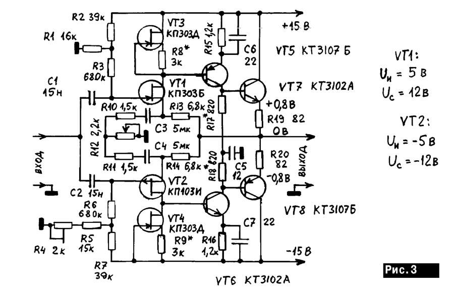


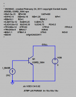
Preamp from Matyushkin, magazine "RadioAmator", #8-9, 1998.
????????????? ????????? - ?????????????, ???????????, ??????? - ????? ?? ????????????????
Attachments
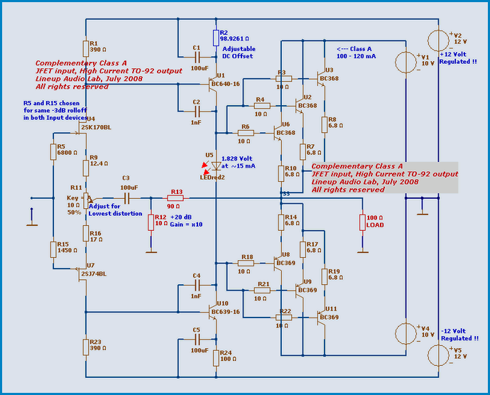
We can arrange the transistors is a little different.Here's a circuit I've played with using Bob Cordell's SPICE models. BC550 and 560 only. First stage input bias currents are NOT negligible so either AC couple it, or build a DC servo.
Bandwidth is 4.7 Megahertz at gain = 21X ((R13+R14)/R14) , therefore gain bandwidth product is 98 MHz (!).
Consider heatsinking the output stage.
An externally hosted image should be here but it was not working when we last tested it.
http://i.fpicture.ru/img/2016-12/13/5850607a20fbc693455045fa.png
Then we get a dept of NFB of 120 dB in the audio range, and 105 dB at the edges.
An externally hosted image should be here but it was not working when we last tested it.
This preamp, except for very small distortions, has the advantage that does not introduce distortion when it works with the volume controls a lot of resistance.
Attachments
Last edited:
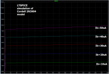
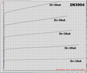
I think those Cordell models might be a little optimistic about output conductance (hybrid pi parameter "ro"), also called Early Voltage.
The 2N3904's model says "VAF=400" but when I measured a real 2N3904 on my curve tracer ten minutes ago, I see an Early Voltage of about 125. Not 400!
Here's an LTSPICE simulation using the Cordell model, and the corresponding measurement on a real device in my lab. The real device has much worse output conductance than the simulation model.
So, be careful with circuits that operate 2N3904s as common emitter amplifiers with high impedance loads, especially current source loads! Such as, unfortunately, Q12 in the attachment to_ post #323.
Attachments
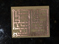
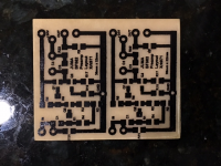
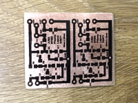
Here is what I am going to print with (35mm x 22mm):
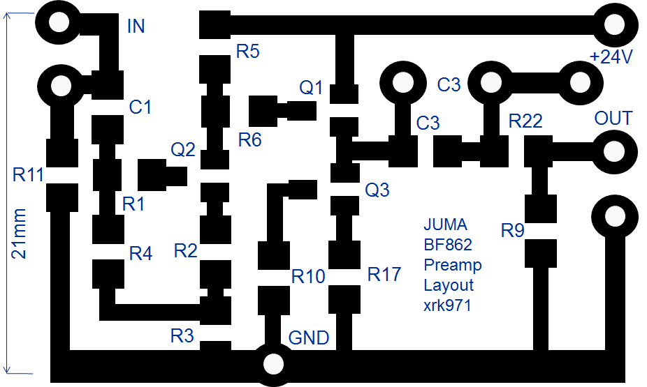
Iron transfer etching worked like a charm and took less than 30min start to finish.
Step 1 - iron on transfer to copper:

Step 2 - etch in 1 part HCl (muriatic acid) & 2 parts H2O2 (5% hydrogen peroxide) bath for 20 minutes:

Step 3 - Remove from etchant and rinse (laserprinter transfer toner still on copper):

Step 4 - Clean off toner with paper towel and "Goop" chewing gum remover:
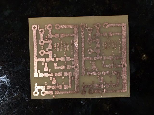
Done. Nice clean features and ready for drilling and soldering.
Attachments
Last edited:
nice going x. clean etching job!.Iron transfer etching worked like a charm and took less than 30min start to finish.
Step 1 - iron on transfer to copper:
Step 2 - etch in 1 part HCl (muriatic acid) & 2 parts H2O2 (5% hydrogen peroxide) bath for 20 minutes:
Step 3 - Remove from etchant and rinse (laserprinter transfer toner still on copper):
Step 4 - Clean off toner with paper towel and "Goop" chewing gum remover:
Done. Nice clean features and ready for drilling and soldering.
Thanks, Prasi! This was fun, I can't believe how fast it is to do a small job like a pre-amp. Layout done using PowerPoint 😀 I am too dumb to use Eagle or Sprint. 🙂
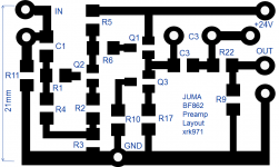
Juma BF862 preamp build
I built up the preamp as shown in the schematic with a few changes: inout cap is 100nF X7R SMT plus a bypass 22nF film cap; output cap is 100nF X7R SMT plus 10uF 50v MLCC and 1uF 230v film cap bypass. I connected it to a 20v supply and first listening impression is that it needs a quiet PSU (regulated and with cap Mx), but I don't hear much gain, and it sounds distorted. I wonder if it's all the SMT 100nF X7R caps I have in the signal path? Or under voltage?
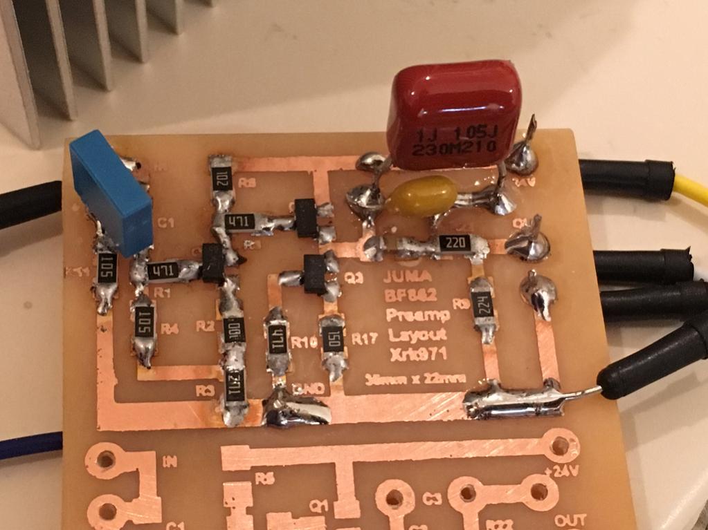
I built up the preamp as shown in the schematic with a few changes: inout cap is 100nF X7R SMT plus a bypass 22nF film cap; output cap is 100nF X7R SMT plus 10uF 50v MLCC and 1uF 230v film cap bypass. I connected it to a 20v supply and first listening impression is that it needs a quiet PSU (regulated and with cap Mx), but I don't hear much gain, and it sounds distorted. I wonder if it's all the SMT 100nF X7R caps I have in the signal path? Or under voltage?
Attachments

Yes, you are absolutely right. I found this line in the library. 3904: VAF = 400, but 3906: VAF = 40. Apparently, Bob was a little mistake when he was typing. I changed the text to 3904: VAF = 100 and repeated the analysis, but the frequency response is almost unchanged. Lost 2 dB from 120 dB in the audible range and 1 dB at the frequency 20 kHz.I think those Cordell models might be a little optimistic about output conductance (hybrid pi parameter "ro"), also called Early Voltage.
The 2N3904's model says "VAF=400" but when I measured a real 2N3904 on my curve tracer ten minutes ago, I see an Early Voltage of about 125. Not 400!
Here's an LTSPICE simulation using the Cordell model, and the corresponding measurement on a real device in my lab. The real device has much worse output conductance than the simulation model.
So, be careful with circuits that operate 2N3904s as common emitter amplifiers with high impedance loads, especially current source loads! Such as, unfortunately, Q12 in the attachment to_ post #323.
Last edited:
1. What voltage (ref. to GND) do you have on the drain of Q2 (input JFET) ?... I don't hear much gain, and it sounds distorted...
2. What's the value of R3 and what's the voltage across it ?
3. What's the voltage across R7 (15 R) ?
4. Whats the voltage (ref. to GND) at the source of Q1 (Drain of Q3) ?
5. Did you measure the Idss of your JFETs - the values in circuit are JFETs with Idss of 12-15mA and very clean 24V PSU ?
Xr,
your selection of output DC blocking capacitors seems overly complex.
What load impedance does this pre-amp need to drive?
What capacitances does it need to drive?
Select a single blocking capacitor that gives an F-3dB ~ 2Hz if a plastic type. Use a voltage rating ~ twice the rail voltage of the pre. I'd be using a 1uF MKT 63V as the DC blocking capacitor to feed into a 100k load, with less than 50pF of parasitics.
If you need to use an electrolytic because your load is down around 10k to 20k, then select a 50V giving an F-3dB ~ 1Hz.
Or use two in series back to back but you need to use double the value.
eg for electrolytic back to back
Load = 10k.
C = 1 / 2 / Pi / Load / 1Hz = 15.9µF
use two 33µF 50V giving an effective 16.5µF 50V
Last edited:
1. What voltage (ref. to GND) do you have on the drain of Q2 (input JFET) ?
2. What's the value of R3 and what's the voltage across it ?
3. What's the voltage across R7 (15 R) ?
4. Whats the voltage (ref. to GND) at the source of Q1 (Drain of Q3) ?
5. Did you measure the Idss of your JFETs - the values in circuit are JFETs with Idss of 12-15mA and very clean 24V PSU ?
Hi Juma,
Thanks for helping me debug.
The photo shows the values of resistors but I will have to get in lab to measure voltages.
R3 is 270R, R7 (I mislabeled R17) is 15R, I did not measure Idss as I don't have a rig that can take SOT23's. I have one for throu hole parts. I could solder one up to a converter and measure it and hope it's representative of the whole roll of parts. I will give it a clean PSU on final setup. Won't have measurements until later tonight.
Ok snuck in lab before leaving today. With inputs grounded and clean (relatively) 24.0v PSU I have following:
V across R7 is 185mV, R7 is indeed 15R
D of Q2 is 6.85v ref to gnd and S of Q2 is 4.75v ref to gnd
S of Q1 and D of Q2 is 7.19v
V across R3 is 4.58v, R3 is 270R
V across R7 is 185mV, R7 is indeed 15R
D of Q2 is 6.85v ref to gnd and S of Q2 is 4.75v ref to gnd
S of Q1 and D of Q2 is 7.19v
V across R3 is 4.58v, R3 is 270R
Xr,
your selection of output DC blocking capacitors seems overly complex.
What load impedance does this pre-amp need to drive?
What capacitances does it need to drive?
Select a single blocking capacitor that gives an F-3dB ~ 2Hz if a plastic type. Use a voltage rating ~ twice the rail voltage of the pre. I'd be using a 1uF MKT 63V as the DC blocking capacitor to feed into a 100k load, with less than 50pF of parasitics.
If you need to use an electrolytic because your load is down around 10k to 20k, then select a 50V giving an F-3dB ~ 1Hz.
Or use two in series back to back but you need to use double the value.
eg for electrolytic back to back
Load = 10k.
C = 1 / 2 / Pi / Load / 1Hz = 15.9µF
use two 33µF 50V giving an effective 16.5µF 50V
It's going to drive the JFET input of my DAO head amp which has high impedance. Can be whatever I set resistor to. Say 100k or 47k etc. So your suggestion of 1uF film is good. I have 1uF 230v MKT installed already. If I set 100k load to be driven. Although Juma set the values on schematic which had 220k load already. I can remove 100nF X7R and 10uF MLCC. On input I can remove 100nF X7R and 22nF film and replace with single 100nF 63v film.
Looks like Q2 is running about 17 mA, seems to be on the higher side Idss wise. That's pushing voltages a bit low with a 1k resistor up there. Try something more like 680-820R.
PSRR of this kind of circuit is fairly lousy since the output voltage of the first stage is directly referenced to the positive rail via the 1k resistor and there is not much feedback going on. You'd probably be better off replacing that resistor by an adjustable current source and using voltage feedback to set gain, reducing the 270R in the process. That does make it inverting though. Plan B, reshuffle the 10R / 270R values (increasing the 10R) so Q2 runs at lower Id.
Often a "simple" circuit means something rather susceptible to component tolerances and graced by other quirks.
Last edited:
How many other mistakes do those models contain? We have seen they are imperfect; how many imperfections are present?Apparently, Bob was a little mistake when he was typing.
How will you simulate the variability of semiconductor characteristics? Low frequency beta is specified on datasheets as a range, but SPICE only simulates one numerical value of beta. Transition frequency fT is specified as a range, but SPICE only simulates one value of fT.
How can you know whether your simulations critically depend upon a certain specific number in a .MODEL, which may or may not match real life semiconductors?
Ok snuck in lab before leaving today. With inputs grounded and clean (relatively) 24.0v PSU I have following:
V across R7 is 185mV, R7 is indeed 15R
D of Q2 is 6.85v ref to gnd and S of Q2 is 4.75v ref to gnd
S of Q1 and D of Q2 is 7.19v
V across R3 is 4.58v, R3 is 270R
Your Q2 has Idss of about 20mA so you should increase R2 (start with 22 R instead of 10 R) until you get about 2.7 V across R3 i.e. about 13 V at the drain of Q2 (with 24V PSU).
How can you know whether your simulations critically depend upon a certain specific number in a .MODEL, which may or may not match real life semiconductors?
Your concern is understandable. I, too, care about such matters.
In the recent past, even missiles and nuclear reactions were calculated on a mechanical adding machine. Parameres amplifiers calculate on paper and it was art.
I think that in the near future there will be simulations that take into account changes of transistor parameters from their conditions of work.
Amplifier, which was shown above, was melted and measured in the amount of several dozen copies. Before this the amp of similar circuitry has been used Alex Nikitin from London to create poweramp from the company Creek Audio or Cambridge Audio, with whom he worked.
In addition to modeling, we have ancient methods of test of amplifiers. These methods are confirmed by simulation results. I can say that the coincidence of these models with measurements is very good up to about 0.000,1% to 40 V / 8 Ohms at a frequency of 20 kHz for poweramp. On the level of distortion below this begins to influence the imperfection of selection of pairs of transistors in the LTP (differential cascades), the interference from the output stages and even the nonlinearity of the resistors of the voltage.
Amplifier, which was shown above, was melted and measured in the amount of several dozen copies. Before this the amp of similar circuitry has been used Alex Nikitin from London http://www.ant-audio.co.uk/ to create poweramp from the company Creek Audio or Cambridge Audio, with whom he worked.
Attachments
Last edited:
Thank you for the tips Juma. I will adjust values as you suggest. So if running lower voltage rail, say 20v then adjust as needed but what is criteria?
- Home
- Source & Line
- Analog Line Level
- Transistor Preamp