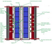


Hello Solhaga, this is what i had in mind to keep the magnets in place and to prevent the steel from bending.
This looks fabulous, it´ll be a great motor!
Perhaps it is a Serguoid!
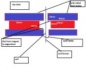
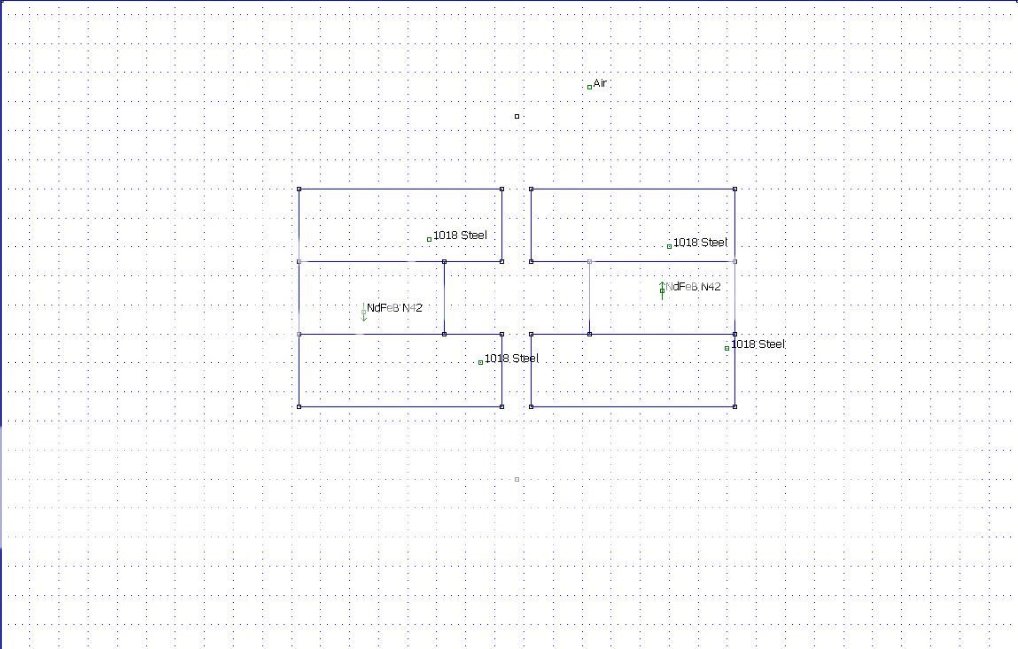
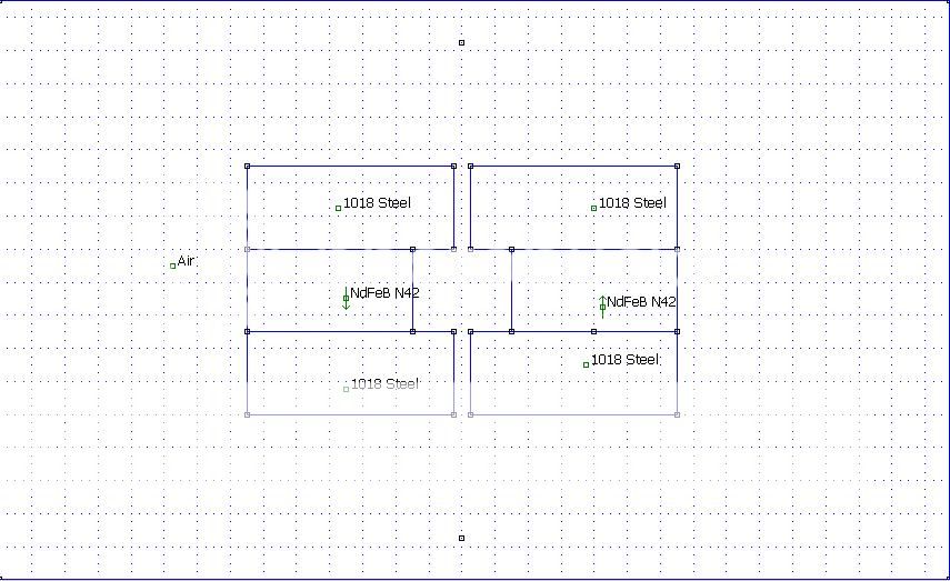
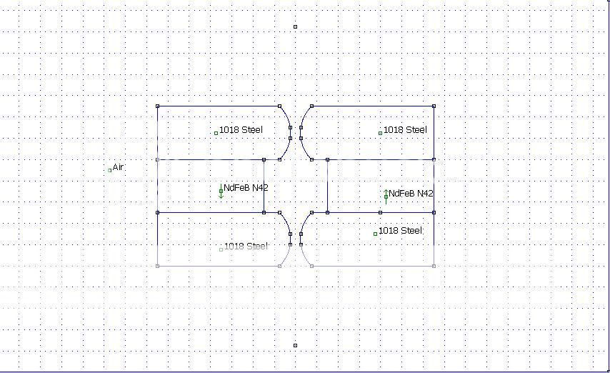
Here's a simpler motor:

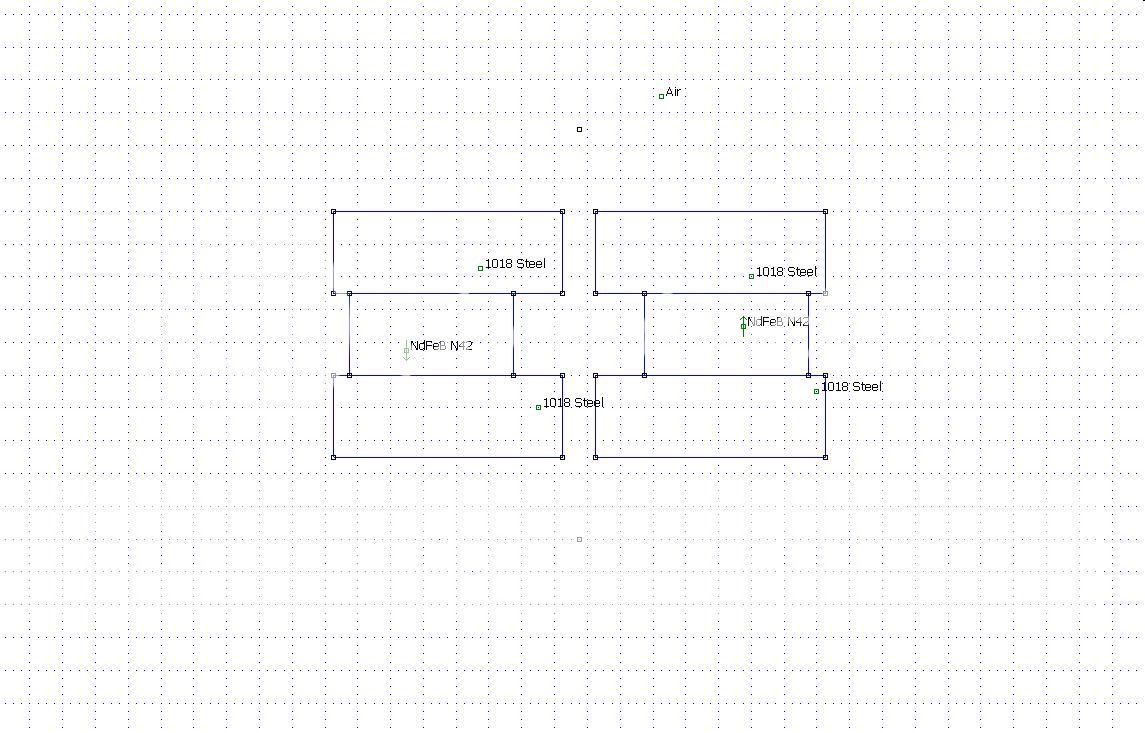
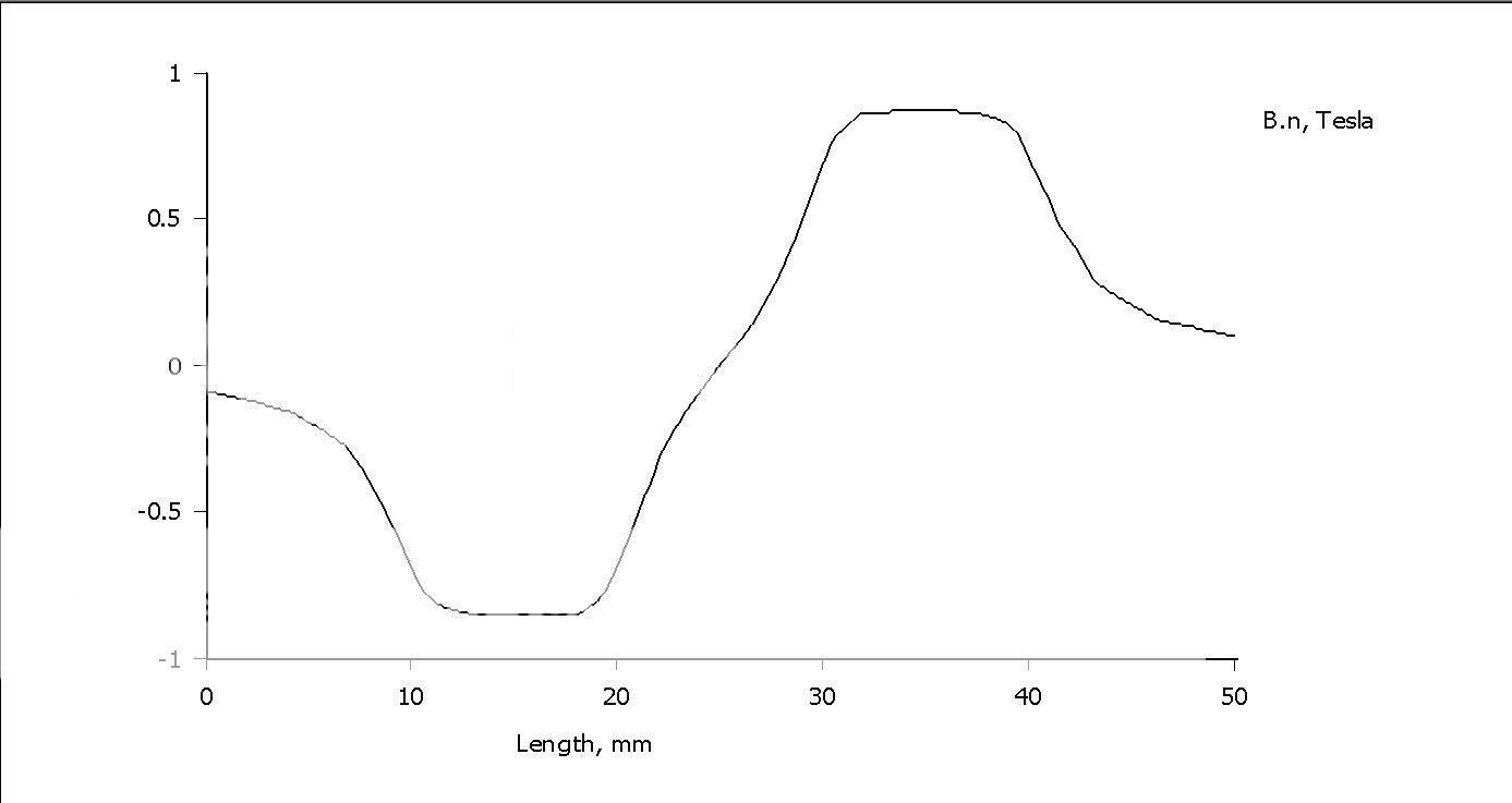
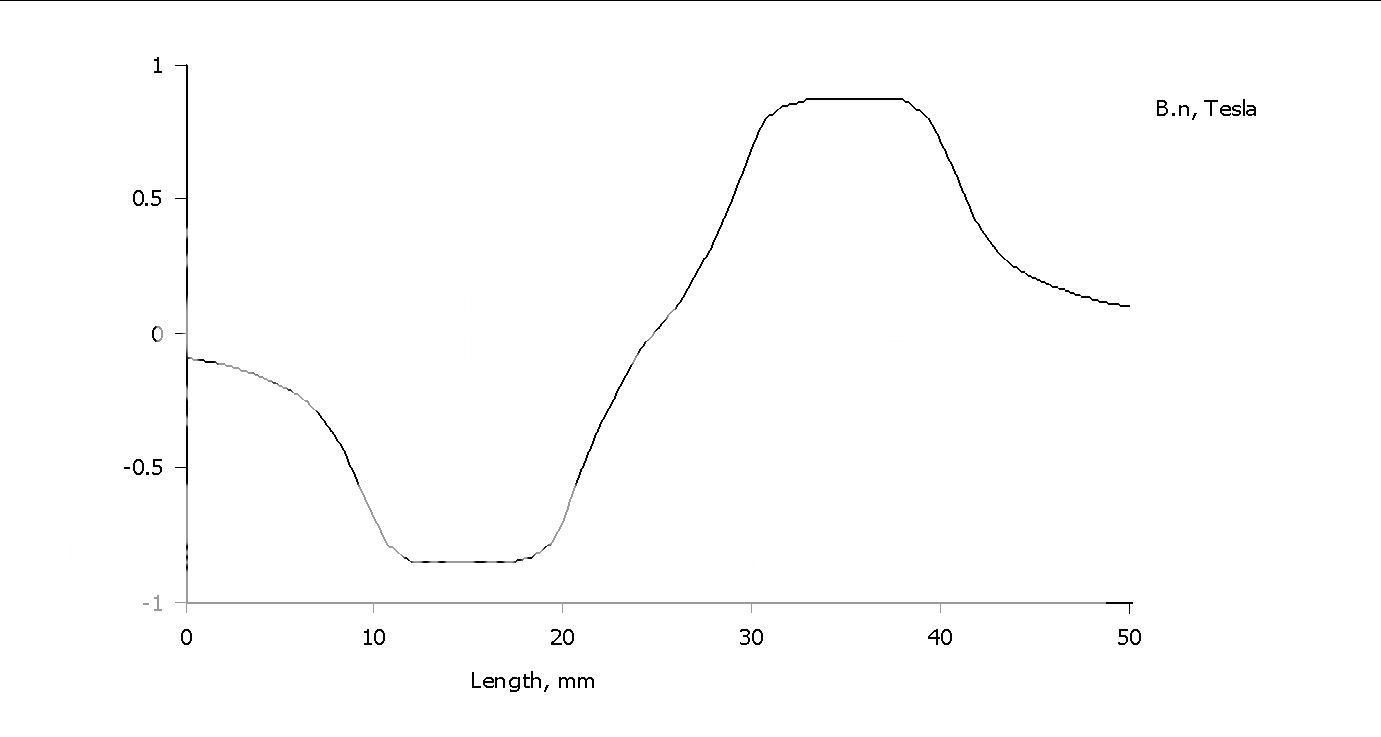
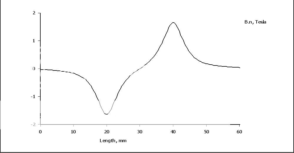
With rounded gap, note that the height now is much smaller and not that linear:

Serguoid... Hehehe!
Thank you very much my friend.
I have another question, what gap or dims do you have in the sims from above (quoted from post 914) that you reached almost 1.3~1.4T and what gap or dims do you use now here in case 1 and 2 (post 922) that you dont have at least 1T? Strange thing..
Thanks
Sergiu
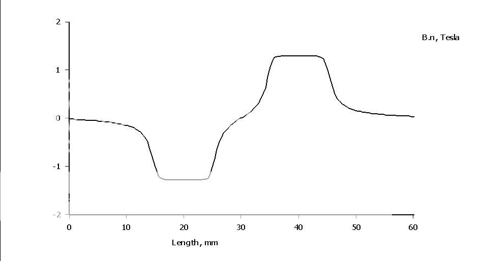
Case 1 and 2 are according to your dimensions given in post #917.
The gap is 3 mm in post #914.
Although not a complete and all correct analogy, you can think of the magnetic flux density as water coming from a barrel of water (the magnet) via a water hose (the pole piece).
It's all about to avoid all the leaks and bends that can dampen the flux.
And then put a thumb over the water hose's end...
Last edited:
Serguoid... Hehehe!
...
Sergiu
Sorry, I meant Sergiuod.
Perhaps Sergiod for short is even better.
No problem my friend. Thanks for the sims again.
It seems that the guy (old man) from cnc misunderstood the drawing and drilled allot of holes altought i explained 3 times.... 🙂))
Anyway i redo the drawing and things changed. I'll show you when i come home from work.
Cheers
Sergiz
It seems that the guy (old man) from cnc misunderstood the drawing and drilled allot of holes altought i explained 3 times.... 🙂))
Anyway i redo the drawing and things changed. I'll show you when i come home from work.
Cheers
Sergiz
Case 1 and 2 are according to your dimensions given in post #917.
The gap is 3 mm in post #914.
Although not a complete and all correct analogy, you can think of the magnetic flux density as water coming from a barrel of water (the magnet) via a water hose (the pole piece).
It's all about to avoid all the leaks and bends that can dampen the flux.
And then put a thumb over the water hose's end...
Yes i understand. Very nice comparison. 🙂
Back at it
Good day, gents.
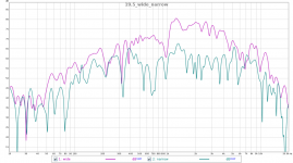
For the membrane, I've given up on Kapton tape and found polycarbonate film that I can get for very little money, especially as compared to Kapton. Attached is a picture of the latest version with a couple frequency response curves. I need help figuring out the right way to measure frequency response. I don't believe those curves.
The motor is completely different from what I see posted here. I used 0.25" x 0.5" x 4" N45 magnets epoxied to the wide side of a 0.5" x 1.5" low carbon steel (1018). The gap is 0.125". I've used 30AWG wire for the coil. The Membranes are 0.10" x 8" x 19.5" polycarbonate (you can only see reflections in the membrane since it's as transparent as glass).
I'm driving them with an 8LS amp from S5 electronics (http://s5electronics.com/l8stereo.html). I've also hooked them up to my kid's modern multi-channel SS receiver. They sound much differently depending on the amp they're hooked up to - the SS amp produces much better bass response.
The frequency response curve is with the 8LS amp. I can't collect a curve with my kid's amp as I'd have to move far too much equipment. I have to believe that the type of amp used for generating the curve makes a difference based on the fact that the speakers sound so different when powered by my kid's amp.
How do I account for coloration from the amp in the frequency response curve? I realize we can't really do a reference standard test, but without good measurements, I can't properly assess the affect of changes to the design.
Good day, gents.
For the membrane, I've given up on Kapton tape and found polycarbonate film that I can get for very little money, especially as compared to Kapton. Attached is a picture of the latest version with a couple frequency response curves. I need help figuring out the right way to measure frequency response. I don't believe those curves.
The motor is completely different from what I see posted here. I used 0.25" x 0.5" x 4" N45 magnets epoxied to the wide side of a 0.5" x 1.5" low carbon steel (1018). The gap is 0.125". I've used 30AWG wire for the coil. The Membranes are 0.10" x 8" x 19.5" polycarbonate (you can only see reflections in the membrane since it's as transparent as glass).
I'm driving them with an 8LS amp from S5 electronics (http://s5electronics.com/l8stereo.html). I've also hooked them up to my kid's modern multi-channel SS receiver. They sound much differently depending on the amp they're hooked up to - the SS amp produces much better bass response.
The frequency response curve is with the 8LS amp. I can't collect a curve with my kid's amp as I'd have to move far too much equipment. I have to believe that the type of amp used for generating the curve makes a difference based on the fact that the speakers sound so different when powered by my kid's amp.
How do I account for coloration from the amp in the frequency response curve? I realize we can't really do a reference standard test, but without good measurements, I can't properly assess the affect of changes to the design.
Attachments
Hi Snot,
Your ruban looks very profi. Nice work. It seems that you have to measure your amp, or include the amp in the calibration loop used when calibrating.
Cheers
Sergiu
Your ruban looks very profi. Nice work. It seems that you have to measure your amp, or include the amp in the calibration loop used when calibrating.
Cheers
Sergiu
Sorry, I meant Sergiuod.
Perhaps Sergiod for short is even better.
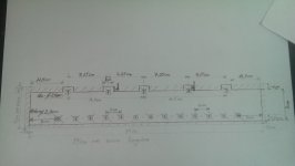
Hello Solhaga,
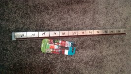
Look what the idiots did... 🙂) An almost different thing!!
I laught but i think i should cry also. I drew some earings in the initial drawing, so practically, they should have cuted out the surplus to leave those earings there, but instead, because it seemd allot of hard work, the boys eliminated those ears so i had to modify the project as seen in the pics bellow.
I have a question if you can help: what do you say, is it ok to put aisi 1017 screws in front of the magnets (instead of the Al 10*10mm square rod)? Will these screws short circuit the magnetic field?
I draw a scetch bellow so that you can make an ideea of what i meant.
Thanks in advance.
Cheers
Sergiu
Attachments


Hello guys,
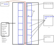
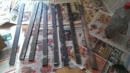
I'm back at last.. This time with a fresh start. I eliminate the square Al pipe from the front of the magnets and use 0.5mm slim textolit (like the one used on the very old "in air" valve amps layouts) .
I still have to put magnets on one rod (just finished three as seen in the pic). Now i have eliminated the surplus of materials and will have a 3mm gap as in the past and the magnets as close as 6 mm from the edge of the steel plate.
Aftter i will finish the assembly i still have to find a good reinforcement so that will keep the steel plates away from bending.
Cheers
Sergiu
Attachments

Hi serg ! nice, you should gain some spl i guess 🙂 not that you needed that with this much power 🙂 but welcome back my frend!
and be carefull !!!!
and be carefull !!!!
well it becomes harder and harder to gain anything. 🙁 doubling the field is out of the question after a while.
Yeah, you're right. If i had a PA bass for open baffle with a bit more xmax, i would have leaved the rubans as they where...but the bass that i have doesnt have huge xmax, instead it has high spl forcing me to go to ported or a huuge enclosure for infinite bafle... IB bass is also a good thing but i'll loose abit of spatiality. I think that in the end there has to be some compromises that needs to be done in each enclosure design/combo. 🙁
Cheers
Sergiu
Cheers
Sergiu
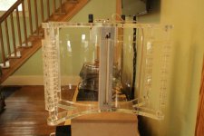
Well, the plates are all assembled and very preciselly alligned and painted. I'm still thinking at something to reinforce each half motor so that it wouldnt bend at the finall assembly..
Cheers
Sergiu
Cheers
Sergiu
I forgot to tel that we know that site and our ruban researched here allready breaks the 20khz by himself and who knows how high it goes (my hardware doesnt measure higher than 23khz)... The only problem is in how flat they go (the one from that site and the one researched here). And this was the 1mil dollars problem hehehe. 🙄
Cheers
Sergiu
As far as i haved seen full range speakers are full range frecv and impedance beasts and these speakers are the same from my point of view but i have to admit that they do sound fantastic and made me to relisten to all my music collection again.😎
There is still an interesting phenomena hapening from aprox 30cm dist from the speakers membranes (a peak wich apears only in measurements) wich needs a different aproach (that we didnt find yet and if i look closer, neither AudioNec). 😱
Cheers
Sergiu
There is still an interesting phenomena hapening from aprox 30cm dist from the speakers membranes (a peak wich apears only in measurements) wich needs a different aproach (that we didnt find yet and if i look closer, neither AudioNec). 😱
Cheers
Sergiu
- Home
- Loudspeakers
- Planars & Exotics
- A DIY Ribbon Speaker of a different Kind