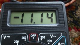
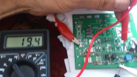
I have now test the current source and the zener of 15 before it, the zener did blow in 5 minutes while the dissipation was just 26 mW with 30 volts and a 1.5 Khz resistor, it looks these chinese zeners are very bad, now I understand why she did blow all the time. It did work for 5 minutes and stopped, faint away.
I do not understand why these chinese rip of people all the time, just ebay and others need to get more action against it.
As you see cheap is sometimes expensive.
I have not yet audio, I am on the begin, ooo X do put a half wat zener in for D4 or a 1 watt.
I await some stuff, and Go check if the zeners are not very low wattages, most are 250mW so blwoing on 26 mW is suspicious.
My Zeners are supposedly 1w - thick sturdy metal leads and large glass envelope. We will see.
My have very thin leads, and is a set of 330 pieces, I think she are not well, strange that these are some kind of fake production because it cost more to produce and sell cheap.
I have send them a message, and I go step over from ebay to aliexpress because I think it is more trustable there, as I did see with the power transistors.
One of my friends once told me "you buy cheap, you buy twice". You should definitely use Mouser, Digikey, Farnell, Newark, etc... I know they charge if you don't have an order of more than 100$ and sometimes 200$ but between members here, we could definitely help others and add some members parts to our orders when we're over the free shipping mark. I did this a few times already.
Ciao!
Do
Ciao!
Do
ohh I had the meter on current setting and measure over the resistor, did blow the zener.
webmaster remove my complain over chinese please haha.
webmaster remove my complain over chinese please haha.
One of my friends once told me "you buy cheap, you buy twice". You should definitely use Mouser, Digikey, Farnell, Newark, etc... I know they charge if you don't have an order of more than 100$ and sometimes 200$ but between members here, we could definitely help others and add some members parts to our orders when we're over the free shipping mark. I did this a few times already.
Ciao!
Do
I look always to the prise, if it feels like a dream, you will not dream..
But for the D4 diode who feed the current source who need 10 mA we have to use a 1 watt zener to get stable voltage, the others are just 1/2 watt and forD3 maybe a LM336Z precisionzener is a idea if the amp do have unstable bias, so for later care.
I have al the fets like irf zvn from mouser, did make that time a big order, and so have enough of them, I did find out I had some jfets
also ore then I did thought also the double ones from akai amps.
Last edited:
My IRF610/9610, IRFP240, J113 from Digikey. ZVN and SK170 from Aliexpress. But that SK170 has proven itself several builds now so good in my book. That ZVN looks like it's real - just the quality of the epoxy and lettering and pins. But who knows until I get a working amp.
I will try flipping the cap and Zener around to tonight. Actually should throw that cap out probably reversed bias beyond repair.
I will try flipping the cap and Zener around to tonight. Actually should throw that cap out probably reversed bias beyond repair.
I put in new J113's, new ZVN4424's, new 18v zeners, reversed position of 100uF cap (and used new cap) and flipped orientation of negative rail zener nearby. I put a 500R pot where 180R is. Still no luck getting bias current to flow - gates on IRF240 are large negative value -19v. Adjusting pot, I get max of 8.7v across 2.2kohm (R14?) should be 11v for 5mA.
Gates on IRF610/9610 are -19.3v and 28,5v, respectively. Gates of ZVN and 2SK270 is 16.5v.
It's still not working - something strange of DC side of input stage as voltage output to gates is at the rails.
Gates on IRF610/9610 are -19.3v and 28,5v, respectively. Gates of ZVN and 2SK270 is 16.5v.
It's still not working - something strange of DC side of input stage as voltage output to gates is at the rails.
I put in new J113's, new ZVN4424's, new 18v zeners, reversed position of 100uF cap (and used new cap) and flipped orientation of negative rail zener nearby. I put a 500R pot where 180R is. Still no luck getting bias current to flow - gates on IRF240 are large negative value -19v. Adjusting pot, I get max of 8.7v across 2.2kohm (R14?) should be 11v for 5mA.
Gates on IRF610/9610 are -19.3v and 28,5v, respectively. Gates of ZVN and 2SK270 is 16.5v.
It's still not working - something strange of DC side of input stage as voltage output to gates is at the rails.
Remove the power fets, measure over R15 and R14 both need the same volatge ootherwise output go to rail voltage, 19.3 and 28,5 is much to much different, both need the same, is adjustable with the pot R23, how much resistance is R23 pot on 2sk170?. measure also over the zener you have flipped, I have lowering here the resistor to 1k for 1/2 watt zener and it works fine, these are the things you need to test first, did you have put one of the differential inputs to ground? how is it possible you get voltages on the 2sk170 jfets? these are inputs need 0 volt otherwise 2sk170 is broken.
The voltages 19.3 and 28.5 need in sim 24 volts and 24 volts, that do set output to offset 0. R23 pot can be used, but when you have use other value like 500 ohm, it do not work.
Otherwise wait for me, I go start as soon I have the parts.
the cap C8 and the zener D4 is on schematic reversed by mistake, it sit on the negative supply with a resistor for lowering voltage current source and limid dissipation, use a 1 watt zener here and lower the resistor to 1k or minimum 820 ohm to get stable voltage.
Mine zeners from the chinese are oke, I was not oke put meter in current setting and measure over the resistor did blow the zener.
regards
When you say remove power FETs do you mean the four IRF610/9610 too? If so, I am better off making up a new amp from bare PCB. The input stage is trivial to build so maybe do that and apply the tweaks and mods you have. One useful tweak is to add tall test point leads with a loop on R14 so you don't do some arc welding like I did with my probe.
Can we outline all the mods needed to get this amp right?
1. Change trace of Q3 and Q4 to connect G of Q3 to S of Q4
2. Flip orientation of 100uF cap and 15v (ok to use 18v here) Zener tied to negative 35v rail
3. Exchange R9 for 500R pot to adjust for 5mA across both R13 and R14 (11.0v drop across 2.2k) ea
4. Use 6.8v Zener diode instead of 6.2v for D3
5. Use non inductive (no wire wound cement) resistors for R28, R29, and R30 - thin film metal or carbon composition resistors (2w ok)
6. Add protection Zener diodes across SMT pads of outputs (please specify value 12v? And combo Zener and 1n4148 or both Zeners?)
7. R32 connect with jumper - no Tempcomp needed yet
8. R17 leave unconnected
9. Do not connect feedback jumpers SV1 and SV2
Last edited:
Point 1 yes that is needed. (mucho lower distortion higher impedances)
Point 2 yes, I did make a fault here in schematic. But zener is not tied to 35 volts line, it blows then, there is a current resistor before that, you have to now, 18 volts do change current settings a little, I think it can be used however the J310 do dissipate more and must provide 10-12 mA, so feel if she get hot, lower then zener to 15 volts, here A TO99 voltage regulator can maybe be better, future thinking.
point 3 just put a pot there, adjust and then set a resistor in place, we have just to do this one time, leaf it there until all is adjusted.
point 4 is also a typo, need to be 6.8 volts, yes is oke if change it everything changes, so keep it 6.8 volts.
point 5 yes, metalfilm or carbon low inductance, no wirewounds, this is also for the feedback resistors R18 and R36, I have change these to 1 K and C3 and C9 to 220pF because you use just 25v volts for power stage, see pictures of sim result.
point 6 yes you need them, irfp has not like the 2sk1058 protection diodes in them, use two zeners 12- 15 volts for each mosfet, look at schematic.
point 7 is oke, not yet a correction, use a 10 ohm or jumper, it do change the idle setting but there is a pot for. R17 can be left open, there is a ptc for later use but maybe the amp do already correct because of the drivers cascodes are on heatsink also, testing.
feedback jumpers has always be connected, or with the output or local on the gates of the circlotron, when open the amp do not work, high open loop gain.
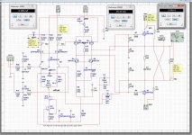
here a schematic of corrections because of you want 25 volt rails for the irfp circlotron, keep in mind the drivers need 16 volts more output for a given loudspeaker output.
corrections do give much lower distortion and amp is faster because of more idle for input to drivers.
I wait for the components and go start soon, maybe waiting for this is a option, I get it to work, I am shure, am experienced with this kind of designing amps, simulation is alsways not excact. I have a ltspice schematic of amp maybe you can play with that and then test further.
Always start stage for stage when build a simmed amp to get voltages and currents right, that is how I do that all the time, current source J310 if adjusted the current in drivers go up or down, and therefore everything is dc connected, and needs time, patient.
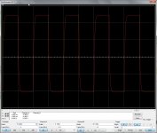
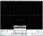
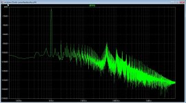
But look at the LTspice distortion picture, nicely only even harmonics because it is a single ended driver to balanced circlotron. picture with square is a 100 Khz, thing go much higher, but have low pass on input to get hf out, limit to 100 Khz bandwidth, that is more then enough.
regards
Point 2 yes, I did make a fault here in schematic. But zener is not tied to 35 volts line, it blows then, there is a current resistor before that, you have to now, 18 volts do change current settings a little, I think it can be used however the J310 do dissipate more and must provide 10-12 mA, so feel if she get hot, lower then zener to 15 volts, here A TO99 voltage regulator can maybe be better, future thinking.
point 3 just put a pot there, adjust and then set a resistor in place, we have just to do this one time, leaf it there until all is adjusted.
point 4 is also a typo, need to be 6.8 volts, yes is oke if change it everything changes, so keep it 6.8 volts.
point 5 yes, metalfilm or carbon low inductance, no wirewounds, this is also for the feedback resistors R18 and R36, I have change these to 1 K and C3 and C9 to 220pF because you use just 25v volts for power stage, see pictures of sim result.
point 6 yes you need them, irfp has not like the 2sk1058 protection diodes in them, use two zeners 12- 15 volts for each mosfet, look at schematic.
point 7 is oke, not yet a correction, use a 10 ohm or jumper, it do change the idle setting but there is a pot for. R17 can be left open, there is a ptc for later use but maybe the amp do already correct because of the drivers cascodes are on heatsink also, testing.
feedback jumpers has always be connected, or with the output or local on the gates of the circlotron, when open the amp do not work, high open loop gain.
here a schematic of corrections because of you want 25 volt rails for the irfp circlotron, keep in mind the drivers need 16 volts more output for a given loudspeaker output.
corrections do give much lower distortion and amp is faster because of more idle for input to drivers.
I wait for the components and go start soon, maybe waiting for this is a option, I get it to work, I am shure, am experienced with this kind of designing amps, simulation is alsways not excact. I have a ltspice schematic of amp maybe you can play with that and then test further.
Always start stage for stage when build a simmed amp to get voltages and currents right, that is how I do that all the time, current source J310 if adjusted the current in drivers go up or down, and therefore everything is dc connected, and needs time, patient.
But look at the LTspice distortion picture, nicely only even harmonics because it is a single ended driver to balanced circlotron. picture with square is a 100 Khz, thing go much higher, but have low pass on input to get hf out, limit to 100 Khz bandwidth, that is more then enough.
regards
Attachments
-
circlotron 25volts currentfeedbacklocal.zip2.8 KB · Views: 60
-
 ScreenHunter_ Sep. 12 14.31.jpg142.9 KB · Views: 203
 -
 ScreenHunter_ Sep. 12 14.35.jpg184.1 KB · Views: 198
 -
 ScreenHunter_ Sep. 12 14.34.jpg21.8 KB · Views: 206
 -
 ScreenHunter_ Sep. 12 14.38.jpg646.7 KB · Views: 206
 -
 ScreenHunter_ Sep. 12 15.10.jpg215.3 KB · Views: 205
Last edited:
The sims look nice - and I expect a very euphonic sound from it. Special quality in fact based on harmonic profile here.
Ok I got point 9 wrong based on what I thought you said. So jumper pin 2 and 3 on SV1 and SV2 to allow feedback to go back to input stage?
I will rebuild slowly from ground up stage by stage again.
I don't have 50R or 100R trim pots yet. Probably should wait until arrive. Should I use J113 or wait for J313?
Hi X
Do not use J113 you need J310 j313 do not excist.
SV1 and SV2 do choose between circlotron output and gate input of these irfp mosfets, making local feedback who however some kind of it already is present on input, it switch between driver output and circlotron output, so when not have powerfets in you can test the driver preamp by set jumper to gate input irfp250 but schematic let see all, just read it.
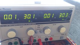
do not start until you have all needed parts, special the pot on 2sk170 need the value I did mention, 100 ohms max, I have choose 50 ohms, do work fine, feedback effect., you can even put a measurement device in current mode and mesure J310 output to trim and ground with -35 volts connected, adjust to 12 mA and then put rest of prestage in.
regards
Do not use J113 you need J310 j313 do not excist.
SV1 and SV2 do choose between circlotron output and gate input of these irfp mosfets, making local feedback who however some kind of it already is present on input, it switch between driver output and circlotron output, so when not have powerfets in you can test the driver preamp by set jumper to gate input irfp250 but schematic let see all, just read it.
do not start until you have all needed parts, special the pot on 2sk170 need the value I did mention, 100 ohms max, I have choose 50 ohms, do work fine, feedback effect., you can even put a measurement device in current mode and mesure J310 output to trim and ground with -35 volts connected, adjust to 12 mA and then put rest of prestage in.
regards
Last edited:
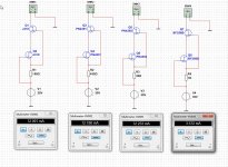
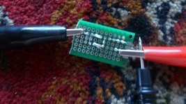
I have test some jfets for the ciclotron input, different jfet and results and used resistor, as you see not all is usable, looks high igss types are the ones to use, and with enough current, the PN4391 PN4392 and PN4393 do work with some different resistors and have enough current capability. and cheap on ebay.
Current mirror with the 2n7000 seem to work.
As you see the BF256 is way out of specs.
Current mirror with the 2n7000 seem to work.
As you see the BF256 is way out of specs.
Attachments
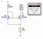
I go test now I have a temperary current source with 2n7000 mosfets, see if I get the same trouble as X did, I think X did get not enough current through the differential input stage, therefore also no current in drivers.
It is hot here, normal 18 oC and now it get 33 a 34 oC very hot for us here special in september.
regards
It is hot here, normal 18 oC and now it get 33 a 34 oC very hot for us here special in september.
regards
Attachments
X
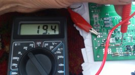
I did test the input section of the amp, it just did work right away, I have used temperely a 1.5 K resistor between the 15 volts zener and the 100 ohm pot between the 2sk170, so you can test it that way however, when do this you need to drive it balanced on both inputs, because the resistor do block unbalanced working, impedance way to low, therefore the need of a cascoded current source.
see pictures, I can finely turn the pot and the voltages on the 2.2k resistors and input section react as predicted, I have set it up to same voltages with pot, works perfecly what means the circlotron is 0 volts offset.
The wilson mirror did not work because the zener supply did suffer, A wilson mirror need 12 mA input for 12 mA output, makes it double for the supply, the zener can not do that, you need 1 watt zener, put it such that it dissipate 650 mWatt then we are safe for fluctuations or other trouble.
It was not that difficult, input stage is also stable, I go later test furher it is pretty hot here in my home.
Update, test if dif amplifies, afcouse as predicted did work, but open loop did make it terrible sensitive. I am on the right track.
regards
Attachments
Last edited:
I have test some jfets for the ciclotron input, different jfet and results and used resistor, as you see not all is usable, looks high igss types are the ones to use, and with enough current, the PN4391 PN4392 and PN4393 do work with some different resistors and have enough current capability. and cheap on ebay.
Current mirror with the 2n7000 seem to work.
As you see the BF256 is way out of specs.
Wilson current,forget it, PN4393 not strong enough, just 5 mA, PN4392 (25 mA) and PN4391 (50 mA) will do, I go for PN9391 do work nicely, maybe a PN4392 bottom fet and a PN4393 on top as some mention, these need to be stable.
I have cancel the PN4393 because these do not work and order 4393 in stead.
now I testing with a 1.5 K resistor.
regards
- Home
- Amplifiers
- Solid State
- allFET circlotron