What voltage will C25 in the output see? That's the 1uF cap across the PD+ and the ND-
Rather low, some 4V DC - that's the overall bias voltage, set by bias spreader.
That's what I thought. That's the only ceramic cap I sent that was rated less that 100VDC. I just wanted to be sure something like that couldn't be causing an issue.
I find it strange that the amp was able to damage a speaker. My bench speakers aren't anything special and I've ran mind quite loud with 63V supplies with no damage. This was directly from a PC though, so nowhere near clipping.
Whatever the case, I'll put together a protection system gift box for Thimios to assemble and try out with some new inputs boards to test.
further test for d.c presence
A protection board(relay based)was added to see what happened.
This circuit publised in Elektor as a part of Crescendo Millennium.
To be more clear only the d.c protect option was connected.
This amplifier comes in protection mode before clipping occurs😡
This protection board activated with +4.5v d.c at least.
Some measurements
Attachments

Last edited:
Have you got any other input boards assembled? We should figure out if the issue is just with the VZ-X4 or if it's with all the inputs.
I'm going to see if I can cobble enough parts together to get mine running for some further testing. I had some issues with an earlier board tripping DC protection intermittently with no explanation, my DC protection board had some overheating resistors on 75V rails at that point, so I assumed it was a false alarm. I had no issues with the modular boards at all.
I'm going to see if I can cobble enough parts together to get mine running for some further testing. I had some issues with an earlier board tripping DC protection intermittently with no explanation, my DC protection board had some overheating resistors on 75V rails at that point, so I assumed it was a false alarm. I had no issues with the modular boards at all.
A protection board(relay based)was added to see what happened.
This circuit publised in Elektor as a part of Crescendo Millennium.
To be more clear only the d.c protect option was connected.
Amplifier comes in protection mode before clipping occurs😡
This protection board activated with +4.5v d.c at least.
Some measurements
Is this just with the X4 or did other IPS do the same?
EDIT, looks like Jeff and I were typing at the same time.
I have mine finished except for freeing up a heatsink. I should be able to test all three flavors by Monday.
Yes i have the VFA assemled.Have you got any other input boards assembled? We should figure out if the issue is just with the VZ-X4 or if it's with all the inputs.
I'm going to see if I can cobble enough parts together to get mine running for some further testing. I had some issues with an earlier board tripping DC protection intermittently with no explanation, my DC protection board had some overheating resistors on 75V rails at that point, so I assumed it was a false alarm. I had no issues with the modular boards at all.
Strange is that this was tested at +/-30v successfully without damaged speaker😕
Keep in mind that this low voltage(+/-30v) isn't enough for proper bias setting.
Last edited:
I'm curious if it's an input issue, or if something is going wrong in the output non switching section with the higher rail voltage. My PC only puts out 1V(? I never measured) so I wouldn't have driven the output very high on mine. I'm hope to try it with a linestage driving it.
I have mine finished except for freeing up a heatsink. I should be able to test all three flavors by Monday.
I'm looking forward to your test results. I've never had a chance to mount my Mini Modular boards and try them yet.
My first thought was that the loudspeaker was destroyed because of its low power, but this protection situation makes me worry..I'm looking forward to your test results. I've never had a chance to mount my Mini Modular boards and try them yet.
I am going to try it with the MLE21193/94 outputs because I don't have any Sankens. I hope that doesn't skew the results.
My first thought was that the loudspeaker was destroyed because of its low power, but this protection situation makes me worry..
A couple of months ago I smoked on of my JBL 12" woofers because I left the room while I had a new amp playing without DC protection. One of the outputs failed and the speaker saw full rail for I don't know how long. Now I know how to re-cone a JBL. 😡 I don't walk away without speaker protection anymore.
Many people say you can blow a speaker with power but I've never been able to do this playing music unless the amplifier goes DC, even when the speaker is driven with a ridiculously overpowered amplifier. They will sound bad long before they are hurt normally.
I've been thinking of designing a smart bench testing supply to prototype some new ideas for the 21st Century Protection system. I want to make it so it's just a simple plug and play supply with everything built in from bulb limiter to DC detection, so we are less likely to procrastinate and just do a quick test run with no protection.
A very clever idea!I've been thinking of designing a smart bench testing supply to prototype some new ideas for the 21st Century Protection system. I want to make it so it's just a simple plug and play supply with everything built in from bulb limiter to DC detection, so we are less likely to procrastinate and just do a quick test run with no protection.
It'll have a display telling rail voltage, rail currents and heat sink temperatures too. That's what I want to prototype on it.
I've been running the VZ-X4 standalone. I ran sine sweeps from 1kHZ to 20kHZ around clipping with 56V supplies. Everything is good at low frequency, but DC offset starts to climb around 10kHZ and is around -1.25VDC at 20 kHZ.
Last edited:
X4 update
Jeff, that's a good approach, Thimios - let's test the IPS board standalone with no external load.
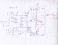
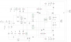
By the way, attached is the updated schematic, running much cooler at lower currents. Changes are are marked by green frames, target voltages across the resistors are marked by red.
But even before implementing the changes - let's see the following:
Test close to clipping at 20KHz, measuring DC in 2 points:
1) IPS output (PD+, ND- and NFB are connected - this is the output);
2) Servo output (OpAmp output) - we need to know if the OpAmp output is reaching the rail (+ or - 15V).
Let's see what's happening. Depending on the result, I see at least two ways to solve the issue.
Jeff, that's a good approach, Thimios - let's test the IPS board standalone with no external load.
By the way, attached is the updated schematic, running much cooler at lower currents. Changes are are marked by green frames, target voltages across the resistors are marked by red.
But even before implementing the changes - let's see the following:
Test close to clipping at 20KHz, measuring DC in 2 points:
1) IPS output (PD+, ND- and NFB are connected - this is the output);
2) Servo output (OpAmp output) - we need to know if the OpAmp output is reaching the rail (+ or - 15V).
Let's see what's happening. Depending on the result, I see at least two ways to solve the issue.
Attachments
The other interesting thing I've found so far is the offset is far worse at sweep than at a steady frequency. 0.3V at steady 20kHZ. I'm trying to test the servo operation now.
The other interesting thing I've found so far is the offset is far worse at sweep than at a steady frequency. 0.3V at steady 20kHZ. I'm trying to test the servo operation now.
Cool. One thing to try - remove R4 and make R5 = 27K.
- Home
- Amplifiers
- Solid State
- Revisiting some "old" ideas from 1970's - IPS, OPS