My servo is putting out around .8V at idle or at 20kHK and through the whole sine sweep.
Meaning, DC at the output increases, but servo doesn't follow?
Let's try the trick with R4, R5. Servo efficiency will increase.
OK, then please put 220uF electrolytic in series with R16 (1k), positive lead closer to ground.
That was the resistor change I was referring to. No difference. Offset still climbs to -1.2V with frequency. Servo output voltage is now fairly steady at .038 - .039V through the sweep.
I've tested the Vertical CFA and the Vertical VFA. Both behave the same on a sine sweep.
The servo seems to become less effective as frequency rises. Output voltage of the servo doesn't change.
The servo seems to become less effective as frequency rises. Output voltage of the servo doesn't change.
I'm sorry to see Thimios loose a woofer.....I am, on the other hand, glad to see the amps stress tested and worked out.
I have a question. What is the 6 pin plug located in the center of the IPS for? Does it need to be connected somewhere?
That's the power connector for the input stage. It plugs into the matching connector on the supply.
OK, I don't understand. Looking at the regulator board schematic I see +-24V. Where does this come from? I also see +- 15V. I believe that is generated by the Rectifier board.
Can you help me understand?
Can you help me understand?
Attachments
Last edited:
The +24V and -24V represent rail voltage in the schematic. Those are the highest value net ports loaded in Diptrace, so that's the number I used.
Yes. Dip trace and most other design software use Netports to connect different parts of the circuit without drawing the actual line, to make it easier to read the schematic. Treat these numbers with the tee under them the same way you treat a ground symbol. All the +24s are joined, -24 are joined, ect.
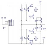
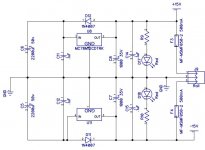
Raw rail AC is rectified and filtered on the rectifier board. Same goes for raw 15VAC. There's no actual power connectors between the boards, they are connected with jumper wires, so there's no power inlet connections shown on the regulator board schematic, just to add to the confusion. Rail power goes through fuses and rail switches (you bypassed the switches on yours) on the regulator board then to output connectors. Rail power is tapped off the output connectors through cap multipliers then to the input board connector. Filtered +/- 15V is jumpered to the regulator board too, and is then regulator and fed to the input board connector too. +/- 15 is tapped off from the input board connector through fuses to a 3 pin header that is meant to power a DC offset detection board for the protection system.
Raw rail AC is rectified and filtered on the rectifier board. Same goes for raw 15VAC. There's no actual power connectors between the boards, they are connected with jumper wires, so there's no power inlet connections shown on the regulator board schematic, just to add to the confusion. Rail power goes through fuses and rail switches (you bypassed the switches on yours) on the regulator board then to output connectors. Rail power is tapped off the output connectors through cap multipliers then to the input board connector. Filtered +/- 15V is jumpered to the regulator board too, and is then regulator and fed to the input board connector too. +/- 15 is tapped off from the input board connector through fuses to a 3 pin header that is meant to power a DC offset detection board for the protection system.
OK, so I am missing some of the boards that were in the grand scheme. That is making it a little confusing. I think I have it now. Thanks
Terry,the first picture in post#1112 may be useful for you,see the gray flat cable.OK, so I am missing some of the boards that were in the grand scheme. That is making it a little confusing. I think I have it now. Thanks
Through this cable the symmetrical stabilized +/-15v, the Gnd connection and the symmetrical rail voltage (after passing the capacitance multiplier) reaches at the input board.
Input stage and servo power supply is +/-15v,VAS power supply is the rail voltage.
Last edited:
OK, so I am missing some of the boards that were in the grand scheme. That is making it a little confusing. I think I have it now. Thanks
What boards are you missing? I think I sent you two rectifier boards and two regulator boards. That's all you need for the supplies.
I've tested the Vertical CFA and the Vertical VFA. Both behave the same on a sine sweep.
The servo seems to become less effective as frequency rises. Output voltage of the servo doesn't change.
This is something I never noticed on my prototype.
I did not measure the DC component during the sweep though. But protection board, doing so and tripping at +/-2V never tripped - any swing, before clipping, in clipping, etc.
If you stop the sweep at, say, 20 KHz, leaving that 20KHz on - does the DC component go down over the time?
Can you measure the same thing during the sweep on some other amps, VHex+ (no servo, but still)?
I'm trying to understand the "phenomenon".
Let's gather some "statistics", testing as many different front-end, as we can.
Thimios, can you also try to see this effect on some other IPS boards / amps you have in hand?
My lab is fully disassembled last week, so I can only simulate and use your info as an input.
I will run some simulations, targeting particularly DC component.
- Home
- Amplifiers
- Solid State
- Revisiting some "old" ideas from 1970's - IPS, OPS