I've put all resistors back to original values, and changed the integrator cap to 1uF. I think DC offset is worse now. I'm seeing -3VDC at 20kHZ steady sine wave. The input is now cold, so this may be affecting the readings. Output of the servo has returned to the same .08V
I connected my Fluke 18 and it shows no DC on the output. My 88 sees it though, and it's freshly calibrated buy Fluke so I think it's more trustworthy.
strange is that i can't measure any difference in the servo controller when hard clipping occurs😕
Both sides of 68k measure 80 mv any time.
Both sides of 68k measure 80 mv any time.
strange is that i can't measure any difference in the servo controller when hard clipping occurs😕
Both sides of 68k measure 80 mv any time.
I'm finding the same measurement. It's as if the servo shuts off at high frequency.
In the opposite side the VFA servo show at the same point 600mv when hard clipping occurs😕I'm finding the same measurement. It's as if the servo shuts off at high frequency.
Thus a scope is the better tool for this test measurement.I wonder if this has to do with the sampling rate of your voltmeters.
Higher sampling rates on the DMM, until the digits are flashing so fast that you can't make out whats up 🙂
One servo test that Bob C. recommends is very low freq at full signal, see where the servo clips. see p 169.
Right, the result very much depends on what exactly you (or Fluke) treat as DC.
That 8V peak - for how long was it there? If some 100mS, it's not DC any more ))
For proper measuring, you need to integrate over some time.
I believe, the attached circuit would be a perfect "calibrated" integrator - exactly the one we use at the input of speaker protection.
That 8V peak - for how long was it there? If some 100mS, it's not DC any more ))
For proper measuring, you need to integrate over some time.
I believe, the attached circuit would be a perfect "calibrated" integrator - exactly the one we use at the input of speaker protection.
Attachments
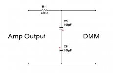
Interesting,i will use this circuit together with an electronic analog voltmeter.Right, the result very much depends on what exactly you (or Fluke) treat as DC.
That 8V peak - for how long was it there? If some 100mS, it's not DC any more ))
For proper measuring, you need to integrate over some time.
I believe, the attached circuit would be a perfect "calibrated" integrator - exactly the one we use at the input of speaker protection.
Can you type on the schematic what voltages expected around servo controller?
One servo test that Bob C. recommends is very low freq at full signal, see where the servo clips. see p 169
I haven't the book,can you explain the procedure?
Last edited:
Exactly 🙂
Makes you wonder if the servo is a better solution or a large AL organic polymer ecap with a small film across it, for the fb loop, as done traditionally. maybe do some tests and compare.
Makes you wonder if the servo is a better solution or a large AL organic polymer ecap with a small film across it, for the fb loop, as done traditionally. maybe do some tests and compare.
Interesting,i will use this circuit together with an electronic analog voltmeter.
Can you type on the schematic what voltages expected around servo controller?
One servo test that Bob C. recommends is very low freq at full signal, see where the servo clips. see p 169
I haven't the book,can you explain the procedure?
The way servo works - it takes the output voltage, integrates over around, say, one second, and compares it to the ground zero. If there is some difference, it starts moving its output voltage (for our inverting case - in direction, opposite to the amp's output voltage polarity), placing the correcting offset to the amplifier's input (that will decrease the offset at the output, until it gets very close to zero).
This thing is working, unless the servo output saturates, coming close to the OpAmp's rails (+/-15V). If it happens, servo does not follow the error signal any more.
So, if DC offset at the OpAmp's output is within, say +/-12V, servo is working - tracking, correcting, etc.
The lower that voltage at the servo's output, the more balanced the amp by itself - showing less error offset at the output and requiring less correction from the servo.
Yes,but why i can't see any different measure than 80mv at the op amp. out when amplifier plays at clipping levels?The way servo works - it takes the output voltage, integrates over around, say, one second, and compares it to the ground zero. If there is some difference, it starts moving its output voltage (for our inverting case - in direction, opposite to the amp's output voltage polarity), placing the correcting offset to the amplifier's input (that will decrease the offset at the output, until it gets very close to zero).
This thing is working, unless the servo output saturates, coming close to the OpAmp's rails (+/-15V). If it happens, servo does not follow the error signal any more.
So, if DC offset at the OpAmp's output is within, say +/-12V, servo is working - tracking, correcting, etc.
The lower that voltage at the servo's output, the more balanced the amp by itself - showing less error offset at the output and requiring less correction from the servo.
Last edited:
I've added the filter to my meter readings. the offset climbs very slowly to 33mV at 20kHZ clipping. Sine sweeps are much improved. hard clipping will creep up to 100mV. This is with the input board running standalone. I can see a test fixture to place the input boards on in the near future. he weight of my test probes keeps unplugging my 100R jumper plug.
With the filter in place, my Fluke 18 reads the DC offset exactly the same. The cap must be charging so it can actually read it now.
With the filter in place, my Fluke 18 reads the DC offset exactly the same. The cap must be charging so it can actually read it now.
Ah! One more thing.
It gave me some hard time last year, until I understood what's going on.
Servo operates with micro-currents at its inputs, at the order of nano-amperes.
I had some remains of the flux in the servo area after soldering the board.
Just a very little bit, almost nothing.
It was enough for some parasitic conduction at the servo input, leading to the wrong correcting signal and pretty high offset at the output.
Moreover, during the troubleshooting, I was moving the oscilloscope leads around, touching that "greasy" area with my fingers, so the offset was changing randomly, exploding my brain 😛
So, the area around the servo must be very clean and dry. Since that time, I particularly clean it and dry with the fan.
I don't know if this may help in our particular case now - just as a bold idea.
I've added the filter to my meter readings. the offset climbs very slowly to 33mV at 20kHZ clipping. Sine sweeps are much improved. hard clipping will creep up to 100mV. This is with the input board running standalone. I can see a test fixture to place the input boards on in the near future. he weight of my test probes keeps unplugging my 100R jumper plug.
With the filter in place, my Fluke 18 reads the DC offset exactly the same. The cap must be charging so it can actually read it now.
Well, this is a rather acceptable level of the offset. Fluctuations within +/-50mV (even +/-100mV) are no harm at all.
I clean everything any time 🙂Ah! One more thing.
It gave me some hard time last year, until I understood what's going on.
Servo operates with micro-currents at its inputs, at the order of nano-amperes.
I had some remains of the flux in the servo area after soldering the board.
Just a very little bit, almost nothing.
It was enough for some parasitic conduction at the servo input, leading to the wrong correcting signal and pretty high offset at the output.
Moreover, during the troubleshooting, I was moving the oscilloscope leads around, touching that "greasy" area with my fingers, so the offset was changing randomly, exploding my brain 😛
So, the area around the servo must be very clean and dry. Since that time, I particularly clean it and dry with the fan.
I don't know if this may help in our particular case now - just as a bold idea.
Any trick for servo test?
lifting the 68k?
Last edited:
I clean everything any time 🙂
Any trick for servo test?
lifting the 68k?
Try the AC filter, you can watch the servo in action quite clearly on the output of the input stage. It's working, but is definitely less effective at hard clipping.
I ran the Vertical CFA with the AC filter in place. The servo was operating acceptably but slow on it. The change to a 1uF cap really picked up the speed of correction. It zeros out faster on power up too.
Why that mean that the servo is working?Try the AC filter, you can watch the servo in action quite clearly on the output of the input stage. It's working, but is definitely less effective at hard clipping.
What i missing?
Last edited:
When I apply a large signal I can watch DC offset appear, then zero itself out. With the 4.7uF cap it's pretty slow at 20kHZ, but with the 1uF cap it's much faster. If I apply a very high input signal (5V P-P) offset slowly climbs, and then creeps back down, then levels off around 35mV.
A fresh test with your DC detection in place and a 1uF integrator cap might solve the triggering issue. Your speaker may have expired in the couple seconds it took for the servo to correct the offset.
A fresh test with your DC detection in place and a 1uF integrator cap might solve the triggering issue. Your speaker may have expired in the couple seconds it took for the servo to correct the offset.
Last edited:
Yes understand now.When I apply a large signal I can watch DC offset appear, then zero itself out. With the 4.7uF cap it's pretty slow at 20kHZ, but with the 1uF cap it's much faster. If I apply a very high input signal (5V P-P) offset slowly climbs, and then creeps back down, then levels off around 35mV
Still i can't explain why my protection board trip before clipping, when his trigger point is at +/-4.7v😕
That's occurred with both IPS,vfa and vz-x4
- Home
- Amplifiers
- Solid State
- Revisiting some "old" ideas from 1970's - IPS, OPS