Transistor recommendations
Gia Sou Thimios,
are you recommending the 2SC3264/2SA1295 Sankens for output transistors over all other types?
Also since you have built a large (huge) number of amplifiers can you recommend the "best" three amplifiers that you have built?
Best regards
Harry
Agree.
Gia Sou Thimios,
are you recommending the 2SC3264/2SA1295 Sankens for output transistors over all other types?
Also since you have built a large (huge) number of amplifiers can you recommend the "best" three amplifiers that you have built?
Best regards
Harry
I generaly aim for 2 to 3mA as well for normal brightness indicator LEDs and for voltage reference LEDs.In the supplies I usually keep them around 10mA for easy math. 4k7 for 48V 5k6 for 56V... Depending on your LED, 2-3mA might be lots if you don't want them glaringly bright.
High brightness LEDs can appear far too bright at this level of current and you may want to look at going as low as 1mA. Test it on a plug board in a dimmed light room some evening.
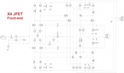
X4 JFET front-end module
OK, here is something we've been missing.
Current-drive family is enhanced by X4 front-end with JFETs at the input.
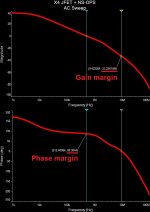
This one provides excellent step response and very accurate waveform reproduction in general. Relatively low global loop gain (38db @ 1KHz) in combination with very high linearity and light compensation - a bit of lag-shunt at VAS output and a bit (almost none) of lead from the output to FB junction point and from the VAS output to FB junction point. Overall THD is less than 0.005% at 20 KHz (20V RMS @ 8 ohm). Low phase shift at the higher end of audio bandwidth. Clean clipping. Huge stability margins (feedback loop analysis is attached). Rather cool thing 😎
It's going to play nicely, although I did not test this particular one as yet.
It will be interesting to see if there will be some audible difference with BJT-based X4 front-end, which is already in production.
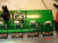
I know, these ones (K246/J103) are hard to find on many territories.
These one are especially good for the input stage because of their low transconductance.
I'm buying as many as I can from the local suppliers right now. They are out of production and I don't see any good complementary alternatives these days.
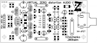
PCBs are available, but only double-layer ones, suitable for NS-Modular.
If somebody is up to designing a single-layer trough-hole one for etching - more than welcome.
Cheers,
Valery
OK, here is something we've been missing.
Current-drive family is enhanced by X4 front-end with JFETs at the input.
This one provides excellent step response and very accurate waveform reproduction in general. Relatively low global loop gain (38db @ 1KHz) in combination with very high linearity and light compensation - a bit of lag-shunt at VAS output and a bit (almost none) of lead from the output to FB junction point and from the VAS output to FB junction point. Overall THD is less than 0.005% at 20 KHz (20V RMS @ 8 ohm). Low phase shift at the higher end of audio bandwidth. Clean clipping. Huge stability margins (feedback loop analysis is attached). Rather cool thing 😎
It's going to play nicely, although I did not test this particular one as yet.
It will be interesting to see if there will be some audible difference with BJT-based X4 front-end, which is already in production.
I know, these ones (K246/J103) are hard to find on many territories.
These one are especially good for the input stage because of their low transconductance.
I'm buying as many as I can from the local suppliers right now. They are out of production and I don't see any good complementary alternatives these days.
PCBs are available, but only double-layer ones, suitable for NS-Modular.
If somebody is up to designing a single-layer trough-hole one for etching - more than welcome.
Cheers,
Valery
Attachments
OK, here is something we've been missing.
Current-drive family is enhanced by X4 front-end with JFETs at the input.
This one provides excellent step response and very accurate waveform reproduction in general. Relatively low global loop gain (38db @ 1KHz) in combination with very high linearity and light compensation - a bit of lag-shunt at VAS output and a bit (almost none) of lead from the output to FB junction point and from the VAS output to FB junction point. Overall THD is less than 0.005% at 20 KHz (20V RMS @ 8 ohm). Low phase shift at the higher end of audio bandwidth. Clean clipping. Huge stability margins (feedback loop analysis is attached). Rather cool thing 😎
It's going to play nicely, although I did not test this particular one as yet.
It will be interesting to see if there will be some audible difference with BJT-based X4 front-end, which is already in production.
😱
I know, these ones (K246/J103) are hard to find on many territories.
These one are especially good for the input stage because of their low transconductance.
I'm buying as many as I can from the local suppliers right now. They are out of production and I don't see any good complementary alternatives these days.
PCBs are available, but only double-layer ones, suitable for NS-Modular.
If somebody is up to designing a single-layer trough-hole one for etching - more than welcome.
Cheers,
Valery
New IPS in the family
I'm populating the regulator. The BOM states MC78M12CDTRK for U8 and MC79M15CDT for U11. One is 12V and the other 15V. Is this intentional?
Thanks, Terry
Thanks, Terry

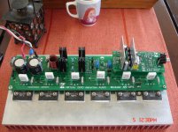

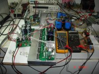
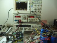
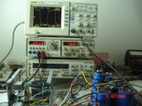
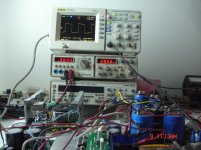
vz-x4 + NS OUT sinusoidal test
Power Supply=+/-50v
74.000uf/rail
Idle current=35mV
Offset=0mV
1V RMS in=27V RMS out on 6R Dummy load=121W RMS/6R (tested at 1KHz)
Power Supply=+/-50v
74.000uf/rail
Idle current=35mV
Offset=0mV
1V RMS in=27V RMS out on 6R Dummy load=121W RMS/6R (tested at 1KHz)
Attachments
Last edited:
Site is down,here is the rest
Attachments
Last edited:
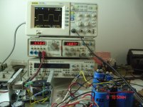
Looking good.
Maybe a square wave? I normally test at 20v peak-to-peak, as the sqr wave drives much more energy and everything becomes rather hot.
Maybe a square wave? I normally test at 20v peak-to-peak, as the sqr wave drives much more energy and everything becomes rather hot.
Coming soon😉Looking good.
Maybe a square wave? I normally test at 20v peak-to-peak, as the sqr wave drives much more energy and everything becomes rather hot.
Last edited:
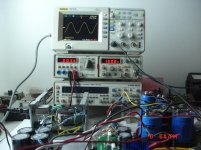
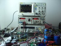
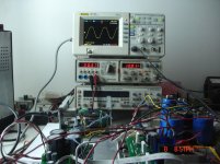
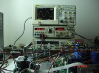
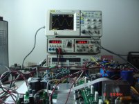
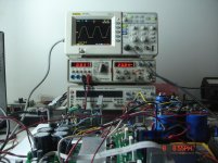
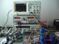
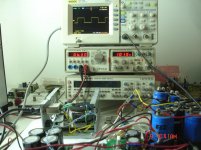
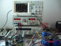
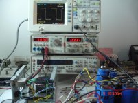
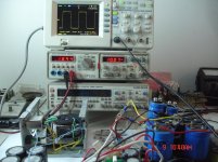
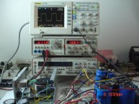
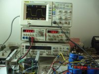
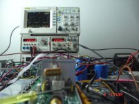
VZ-X 4 square wave test
Peoples love to see square wave😉
Voltmeter show the input voltage.
Read the out voltage on scope.
Read the test frequency on scope or on the function generator.
Peoples love to see square wave😉
Voltmeter show the input voltage.
Read the out voltage on scope.
Read the test frequency on scope or on the function generator.
Attachments
Last edited:
Peoples love to see square wave😉
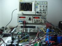
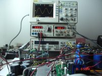
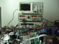
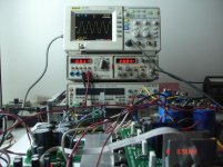
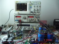
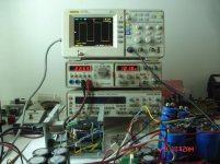
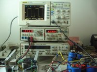
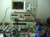
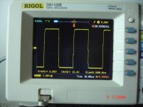
OK, high-precision 1KHz 😎
Ah, ok - more pictures are coming 🙂
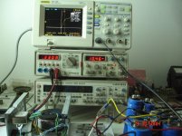
10 KHz looks as expected - compensated for having slightly rounded corners for more reliability in "mass production".
Last edited:
please wait the best is coming😉OK, high-precision 1KHz 😎
The picture before the last is low freq, using 3u3 bipolar as coupling capacitor when the last is direct coupling
Attachments
-
 DSC00282.jpg308 KB · Views: 147
 -
 DSC00281.jpg306.8 KB · Views: 148
 -
 DSC00280.jpg308.9 KB · Views: 179
 -
 DSC00283.jpg294.8 KB · Views: 145
 -
 DSC00284.jpg303.5 KB · Views: 141
 -
 DSC00285.jpg312.2 KB · Views: 141
 -
 DSC00286.jpg314.1 KB · Views: 150
 -
 DSC00287.jpg288.5 KB · Views: 157
 -
 DSC00288.jpg275.1 KB · Views: 182
Last edited:

- Home
- Amplifiers
- Solid State
- Revisiting some "old" ideas from 1970's - IPS, OPS