Get a temperature controlled iron with replaceable tips.
I regularly use the smallest but the radius on the end is far too big. But it works.
I wish I could take a big tip and shape it to a chisel point, but I don't know how to iron plate it to cover up the reshaped copper.
I have a chisel point in my spares box, but it is not quite wide enough and the radius at the tip is too big. I want a real chisel POINT.
There are Youtube videos showing how to solder parts such as TQFP with a massive wedge tip. You lay fine solder(.015") across the pads and just quickly swipe the iron across the row. It actually work quite well if everything is clean enough.
I don't have 0.015" (~26½awg) solder.There are Youtube videos showing how to solder parts such as TQFP with a massive wedge tip. You lay fine solder(.015") across the pads and just quickly swipe the iron across the row. It actually work quite well if everything is clean enough.
I use 22awg and 24awg. I wish a 500g reel of 26awg was much cheaper than £60 !
I don't have 0.015" (~26½awg) solder.
I use 22awg and 24awg. I wish a 500g reel of 26awg was much cheaper than £60 !
The solder size helps a lot. It's much easier to control the amount you apply = less shorts to repair after.
 Off topic posts removed
I hope to ended up the war🙂
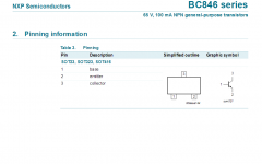
Yes this sot363 dual transistor is smaller to bc846 sot23
Yes it is difficult to solder by hand this sot363
You must solder all pins from the same side together😉
You must solder all pins from the other side together
Then either reflow each side(using flux) keeping the board vertical or use desoldering wire.
I use 0.5mm solder wire
Attachments
Last edited:
it's the same size as the sot23.
It has extra pins.
It is the same height, it is not top heavy.
Because it has extra pins the pins are clsoer together.
Once the device is tacked by one corner pin, it becomes an easy job to solder the other three corner pins. Then properly solder the first pin. None of this is any more difficult than soldering a 3pin sot23.
The bigger problem is applying solder to the middle pin of each group of three.
Jw has described a method of "swiping" and then cleaning out any shorting between the very closely spaced pins.
I prefer to solder the close fitting pins individually. I have done it with a soic 8pin, but this is nearly double the spacing at 0.05".
Last edited:
They are not the same size. Sot363 2.2mm x 2.0mm x 1.1mm. Sot23. 3.0mm x 2.5mm x 1.1
Biggest issue is aligning very narrow pins on very close pads and holding the part still and aligned to get it soldered. Then clearing solder from between the close pads buried berween the narrowly spaced pins.
Biggest issue is aligning very narrow pins on very close pads and holding the part still and aligned to get it soldered. Then clearing solder from between the close pads buried berween the narrowly spaced pins.
it's the same size as the sot23.
It has extra pins.
It is the same height, it is not top heavy.
Because it has extra pins the pins are clsoer together.
Once the device is tacked by one corner pin, it becomes an easy job to solder the other three corner pins. Then properly solder the first pin. None of this is any more difficult than soldering a 3pin sot23.
The bigger problem is applying solder to the middle pin of each group of three.
Jw has described a method of "swiping" and then cleaning out any shorting between the very closely spaced pins.
I prefer to solder the close fitting pins individually. I have done it with a soic 8pin, but this is nearly double the spacing at 0.05".
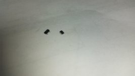
I'm not calling you a liar, but I am telling you they are a different size and they are top heavy
Attachments
Absolutely rightThey are not the same size. Sot363 2.2mm x 2.0mm x 1.1mm. Sot23. 3.0mm x 2.5mm x 1.1
Biggest issue is aligning very narrow pins on very close pads and holding the part still and aligned to get it soldered. Then clearing solder from between the close pads buried berween the narrowly spaced pins.

Aligning is a big issue
Sorry, I pulled up a sot363 datasheet and it specified 2.2mm long.
That looked the same as the sot23.
But your pic clearly shows them as different length.
I'm wrong again.
That looked the same as the sot23.
But your pic clearly shows them as different length.
I'm wrong again.
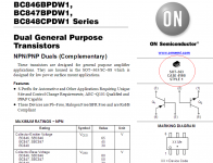
BC846BPDW1T1G dual NPN-PNP. not reported on datta seat as matched devices😕Yes - we can have a matched (and thermally coupled) pair of npn+npn, pnp+pnp, or npn+pnp - whatever we need in particular case - suitable for virtually any kind of a front-end. Lots of freedom for designer.
But there must be some drawback. Difficult to solder manually 🙂 Even SMD opamps - like AD711 - are not that much of a problem as they are slightly bigger.
I'd love to have some more matched-dual or even -quad options available... some C3503/A1381 in a big 6-pin case would be great. As well as some sort of C1845/A992 and N5551/5401 pairs for higher-voltage application. Some jfet pairs would be great. K389 are not produced any more. Just dreaming 😉
Last edited:
Hi Thimios,
Does an amp with Sankens sound better than usual 2SA1943/2SC5200 BJT's? I have never heard one in person.
Does an amp with Sankens sound better than usual 2SA1943/2SC5200 BJT's? I have never heard one in person.
To my opinion yes🙂Hi Thimios,
Does an amp with Sankens sound better than usual 2SA1943/2SC5200 BJT's? I have never heard one in person.
BC846BPDW1T1G dual NPN-PNP. not reported on datta seat as matched devices😕
Hi Thimios,
You are actually right. NPN-NPN and PNP-PNP duals are matched within the package. NPN-PNP ones are complementary, so they are never really matched. However, if you look at the curves in the datasheet, NPN and PNP ones are rather close to each other.
It would be interesting to compare h21 and Vbe measurements within NPN-PNP dual - never really did it.
Although these duals perform very well, so I never felt the need for this kind of comparison 🙂
and they cannot be on the same die.BC846BPDW1T1G dual NPN-PNP. not reported on datta seat as matched devices😕
It is likely they are just two transistors in the package to suit mass production.
They will have one advantage, even when not matched. They will be thermally quite close together.
Agree.and they cannot be on the same die.
It is likely they are just two transistors in the package to suit mass production.
They will have one advantage, even when not matched. They will be thermally quite close together.
I'm getting all the parts I need these boards. Some of the items include the resistors for the LED indicators. They say match to rail voltage. What is the mA you normally shoot for in indicator LEDs?
Thanks, Terry
Thanks, Terry
In the supplies I usually keep them around 10mA for easy math. 4k7 for 48V 5k6 for 56V... Depending on your LED, 2-3mA might be lots if you don't want them glaringly bright.
- Home
- Amplifiers
- Solid State
- Revisiting some "old" ideas from 1970's - IPS, OPS