I argued that case in another Thread. AKSA rubbished that low dissipation view. It still remains my opinion.Hi Duke,
That's why you make the feedback network from multiple identical resistors, one to ground, all the others in series. When you calculate, you will see that all thermals cancel.
Jan
Has nothing to do wit low dissipation. If you have say 1k to ground and 9 x 1k in series, you have 1/10 the signal at the junction.
Now because of heating and/or signal heating modulation, since all Rs are in series, ALL get the same variations in value. Because of that, the ratio at the junction STILL remains 1/10 even when the individual Rs vary all over the place!
Jan
Now because of heating and/or signal heating modulation, since all Rs are in series, ALL get the same variations in value. Because of that, the ratio at the junction STILL remains 1/10 even when the individual Rs vary all over the place!
Jan
and all see the same dissipation, so the same deltaT
Whereas using one resistor with a ten times higher value sees ten times the dissipation and a very different deltaT.
Then maybe it's my lack of eloquence that loses the point.
Whereas using one resistor with a ten times higher value sees ten times the dissipation and a very different deltaT.
Then maybe it's my lack of eloquence that loses the point.
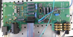
As promised some shots of the autoranger main PCB.
All SMDs are 0805 or 1206. I soldered this with no special tools, just thin solder and a fine iron point.
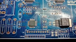
There's one exception: a few dual protection diodes in 3-pin SOT, see for instance D7 top right. These are a bit smaller but still easy enough for my almost 7 decades old eyes!
This is my testing prototype and the final will be slightly different but not much.
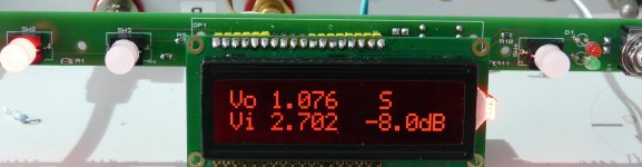
The small control PCB has also some SMDs, plus of course the buttons, on/off switch and display on the front. DIL/header connectors, the DIL28 controller and some TH resistors on the back.
And please, no comments on my soldering proficiency or lack thereof 🙁
Jan
All SMDs are 0805 or 1206. I soldered this with no special tools, just thin solder and a fine iron point.
There's one exception: a few dual protection diodes in 3-pin SOT, see for instance D7 top right. These are a bit smaller but still easy enough for my almost 7 decades old eyes!
This is my testing prototype and the final will be slightly different but not much.
The small control PCB has also some SMDs, plus of course the buttons, on/off switch and display on the front. DIL/header connectors, the DIL28 controller and some TH resistors on the back.
And please, no comments on my soldering proficiency or lack thereof 🙁
Jan
Attachments

Hi Bob,
I use this: https://linearaudio.nl/silentswitcher
Actually this thing is a fall-out of my search for a very low noise, mains-independent supply that I wanted for the Autoranger. Turns out it is a great supply for lots of small-signal things like phono pre's, preamps, DACs, that sort of thing.
Jan
Thanks Jan,
This seems like a really good approach.
Best,
Bob
For those interested in the oven approach there's always these items, which at those prices makes bodging a toaster seem hardly worth the effort...
T962 Reflow Oven Exhaust Fan Included Preheat Mode W/ Windowed Drawer Economical | eBay
Also, iirc, there was a Elektor project a while back about converting a small oven for smd cooking...
T962 Reflow Oven Exhaust Fan Included Preheat Mode W/ Windowed Drawer Economical | eBay
Also, iirc, there was a Elektor project a while back about converting a small oven for smd cooking...
Thanks for the photographs Jan.
I don't see any issues soldering those smd parts, there's not that many and they're not crowded together...
Fwiw, this was my first effort at smd on a parallel dac board from Ebay specifically purchased to ascertain the difficulty of manual smd soldering.
Soldering was done using a Weller WSP-80 pencil with a 1.2mm bent chisel tip, a RS mini fluxer pen and x10 magnification optics. I did initially try a Weller needle tip but found it couldn't deliver enough heat reliably at the point of contact so I went back to the 1.2mm, which I use for most pcb soldering.
Hth and encourages those who haven't been down the manual smd path 😀
Attachments
Has nothing to do wit low dissipation. If you have say 1k to ground and 9 x 1k in series, you have 1/10 the signal at the junction.
Now because of heating and/or signal heating modulation, since all Rs are in series, ALL get the same variations in value. Because of that, the ratio at the junction STILL remains 1/10 even when the individual Rs vary all over the place!
Jan
I have to think about this.
Is it the varying resistance that causes a rise in distortion?
I understand the thermal modulation part but is this the mechanism?
I found some 3900 ppm SMT resistors. I thought they might work similarly to a lamp but with better linearity.
The distortion was through the roof. So I guess not.
Last edited:
As promised some shots of the autoranger main PCB.
All SMDs are 0805 or 1206. I soldered this with no special tools, just thin solder and a fine iron point.
There's one exception: a few dual protection diodes in 3-pin SOT, see for instance D7 top right. These are a bit smaller but still easy enough for my almost 7 decades old eyes!
This is my testing prototype and the final will be slightly different but not much.
The small control PCB has also some SMDs, plus of course the buttons, on/off switch and display on the front. DIL/header connectors, the DIL28 controller and some TH resistors on the back.
And please, no comments on my soldering proficiency or lack thereof 🙁
Jan
Sorry Jan I can't resist.
I thought the soldering was excellent on the sample I got from you.
For those interested in the oven approach there's always these items, which at those prices makes bodging a toaster seem hardly worth the effort...
T962 Reflow Oven Exhaust Fan Included Preheat Mode W/ Windowed Drawer Economical | eBay
Also, iirc, there was a Elektor project a while back about converting a small oven for smd cooking...
Quite cool.
I wonder if induction would work or would that destroy the parts.
Hi Demian,
Anyone want to try the microwave?
Don't! I already know how destructive this is to anything conductive.
-Chris
I don't know which way this method would go, but I can only assume that if it does heat the components and PCB, it will be fairly destructive to the parts and PCB. That could be a lot of fun too!Most likely induction would heat the wrong parts if any.
Anyone want to try the microwave?
Don't! I already know how destructive this is to anything conductive.
-Chris
AFAK the board and components are heated to the same temperature in a large convection oven.
Love the microwave idea. Wish I were wealthy enough to try it.
Of course this a all lot hot air.
Love the microwave idea. Wish I were wealthy enough to try it.
Of course this a all lot hot air.
Last edited:
Hi Demian,
I don't know which way this method would go, but I can only assume that if it does heat the components and PCB, it will be fairly destructive to the parts and PCB. That could be a lot of fun too!
Anyone want to try the microwave?
Don't! I already know how destructive this is to anything conductive.
-Chris
And the oven.
Sorry Jan I can't resist.
I thought the soldering was excellent on the sample I got from you.
That was by a company 😊...
Jan
Here are the two Elektor articles for diy toaster smd aficionados with free pcb layouts and free controller software downloads for both...
SMD Reflow Soldering Oven
https://www.elektormagazine.com/magazine/elektor-200601/18154
Reflow Solder Controller
https://www.elektormagazine.com/magazine/elektor-200712/18676
SMD Reflow Soldering Oven
https://www.elektormagazine.com/magazine/elektor-200601/18154
Reflow Solder Controller
https://www.elektormagazine.com/magazine/elektor-200712/18676
Here are the two Elektor articles for diy toaster smd aficionados with free pcb layouts and free controller software downloads for both...
SMD Reflow Soldering Oven
https://www.elektormagazine.com/magazine/elektor-200601/18154
Reflow Solder Controller
https://www.elektormagazine.com/magazine/elektor-200712/18676
I purchased one of those controlled-heating-curve ovens, similar to the Elektor one.
Used it a few times but the stuff with the stencil and paste got quite messy. Probably my incompetence.
Switched to just soldering them by hand, never looked back 😎
YMMV
Jan
Oh I already do SMT much the way you describe but it is slow and tedious. .
That is really the issue for me with DIY projects.... time. anything slowing me down, I dont do... plenty of other things to do. Then secondary things - like I cant read the value on the various smd parts, slows me down also. etc etc.
THx-RNMarsh
Last edited:
From what I've seen one of the better ways of putting down small batch pcb solder paste is with a pneumatic dispenser, which usually has a pick and place suction function as well, together with a rolling table for resting your arm and moving across left to right with the pcb boards laid out in a grid, but unless you're working on a batch of, say, 4-5 or more pcb's, might as well hand solder...
Having some experience of screen printing from back in the day, I would observe that there is the same set up time and cleaning whether doing one impression or twenty and unless the solder stencil can be stretched on a frame like a silk screen, would expect solder stencilling to be a messy experience, imho...
Having some experience of screen printing from back in the day, I would observe that there is the same set up time and cleaning whether doing one impression or twenty and unless the solder stencil can be stretched on a frame like a silk screen, would expect solder stencilling to be a messy experience, imho...
- Home
- Design & Build
- Equipment & Tools
- QuantAsylum QA400 and QA401