I use a 10mm shaft chucked in a drill. I turn it slowly and just keep the wire taut. If I need bigger or smaller diameter I just use a different size shaft.
AHH, OK, i can try that. Thanks.
Going to be a bit before i can get some more heatsinks. House A/C just needed a Motor. Major $$.
Going to be a bit before i can get some more heatsinks. House A/C just needed a Motor. Major $$.
Prasi,
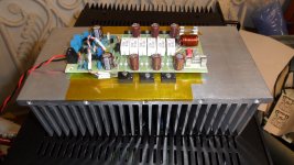
Got both of the boards up and running,+-55V. Still have to get proper heatsinks for them before i can give a proper listen to them. Thank you for the boards.
Rick
Hi Rick nice work🙂. One more thing is 2R2 ground lift does not work DC servo amps as informed by Mr. Mile somewhere here on this thread. So better to remove that and put additional wire from i/p ground to PSU ground. Amp does have a small start-up thump, which a speaker protect with delay will take care of nicely. What bias are you using? I tested upto 90mA before I ran out of heatsink room😀.
reg
Prasi
Prasi,
Thanks for the info. i to ran out of heatsink at 90ma. been digging around in garage & found 2 - 10"L by 5" high with 1.75" fins. Should be big enough. Have to clean em up a bit, before i drill holes.
Rick
Thanks for the info. i to ran out of heatsink at 90ma. been digging around in garage & found 2 - 10"L by 5" high with 1.75" fins. Should be big enough. Have to clean em up a bit, before i drill holes.
Rick
Prasi,
Ok got them mounted. One needs troubleshooting as it blows V+ fuse. other works, but there is no high end and very little middle. sounds muddy. Running it at 90ma. (20mv across a .22 ohm resistor). Do you have a Schematic for this build.
FYI, i did remove the 2r2 and jumper input gnd. to power gnd.
Ok got them mounted. One needs troubleshooting as it blows V+ fuse. other works, but there is no high end and very little middle. sounds muddy. Running it at 90ma. (20mv across a .22 ohm resistor). Do you have a Schematic for this build.
FYI, i did remove the 2r2 and jumper input gnd. to power gnd.
Attachments
Prasi,
Ok got them mounted. One needs troubleshooting as it blows V+ fuse. other works, but there is no high end and very little middle. sounds muddy. Running it at 90ma. (20mv across a .22 ohm resistor). Do you have a Schematic for this build.
FYI, i did remove the 2r2 and jumper input gnd. to power gnd.
Hi Rick,
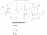
Does the LED glow? Here is the schematic. which op-amp are you using? It should be TL071. are there any replacement parts used?
reg
Prasi
PS schema is quite big in size, sorry for that.
edit: The layout files are in post # 707
Attachments
Last edited:
Prasi,
quick answers for working board.
1- Yes LED Glows
2.- using TL071P
3 - No replacement parts.
i can adj bias with no problem.
Non working board.
1 - NO the LED does not glow
2 - using TL071P
3 - No replacement parts used.
Rick
quick answers for working board.
1- Yes LED Glows
2.- using TL071P
3 - No replacement parts.
i can adj bias with no problem.
Non working board.
1 - NO the LED does not glow
2 - using TL071P
3 - No replacement parts used.
Rick
Prasi,
quick answers for working board.
1- Yes LED Glows
2.- using TL071P
3 - No replacement parts.
i can adj bias with no problem.
Non working board.
1 - NO the LED does not glow
2 - using TL071P
3 - No replacement parts used.
Rick
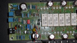
Can you post images of top and bottom of both boards when you get time?
For the working board, my guess is wrong value resistors somewhere.
At the cost of being hackneyed, are you using mains bulb tester when you make changes and connect to power supply?
Reg
Prasi
Last edited:
44250,
yes, led is properly polarized.
Prasi,
i am using 10 ohm 5W resistors on V+ & V- when first powering up to adj bias. Will get boards removed for pics & post in a bit.
Rick
yes, led is properly polarized.
Prasi,
i am using 10 ohm 5W resistors on V+ & V- when first powering up to adj bias. Will get boards removed for pics & post in a bit.
Rick
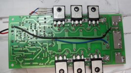
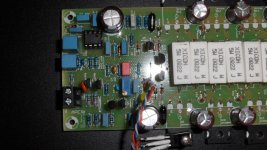

Here is Non Working Board
I had a good look at both of the boards, cant find any thing amiss (BTW nice soldering), dont have eagle eyes.
Non-working board:
1.Pl check the pin 2 and 3 of op amp for any short, which may not be an issue anyway. try reflow of joints if you haven't done that already.
2. see if any of the transistor is exchanged, MPSA 42 to 92, BC327 to 337, IRFP9240 to 240, etc. + you may like to see if any of the semi is dud.
Working board.
1. like I said resistor values check based on the schematic for expected value (if any of the resistor are in parallel.
hope that someone like Mr. Mile is able spot something.
how is the DC offset behavior , might give some indication if the problem like with servo ckt.
Last edited:
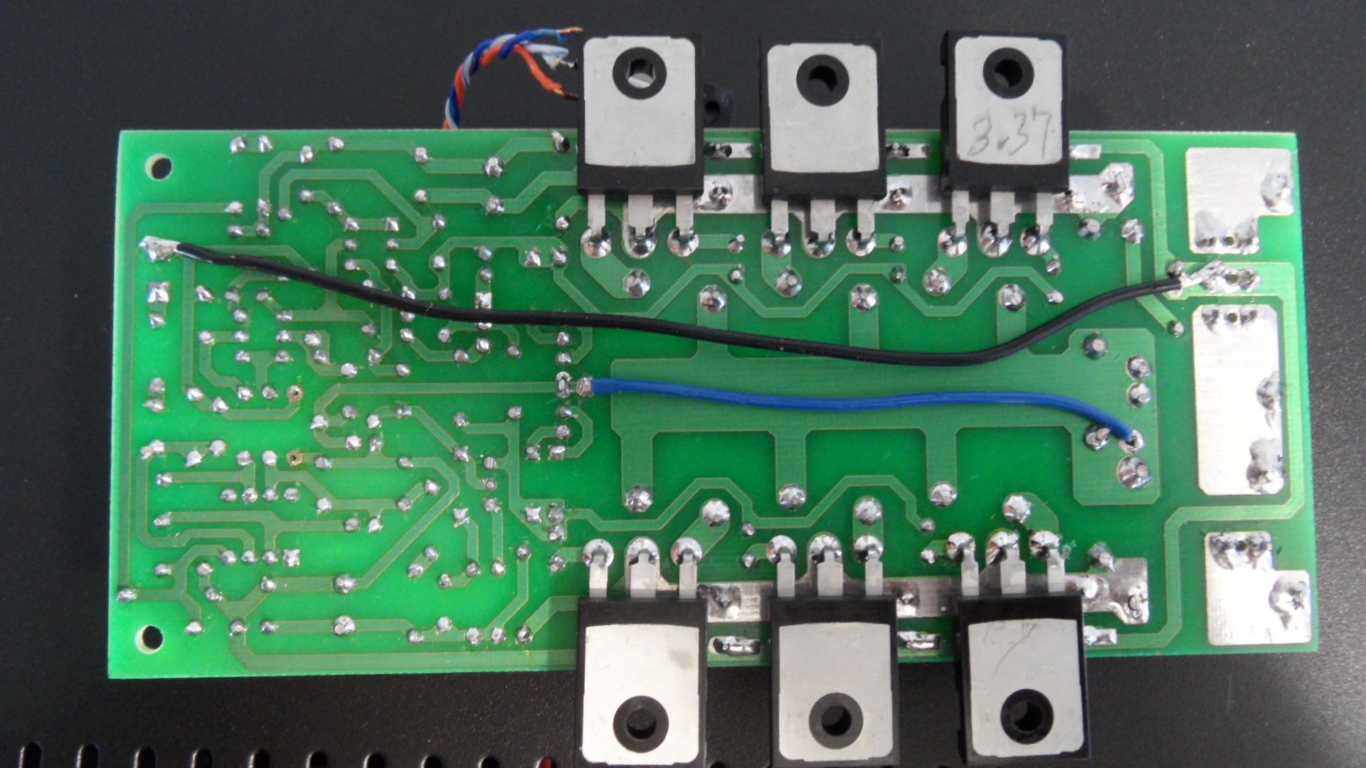
Blue wire on non working board looks like cold solder joint and only connected to one pad. On good board it is connected to two pads on right. ? Why the difference?
Prasi,
Found problem on working board. I had put a 22nf cap in C7. Should have been a 22pf cap. Sounds Lovely now.
Still haven't found problem with other board. Weird part is i had it working. i adj bias on small heatsink with no problems. Problem started after i mounted it on Large Heatsink.
XRK,
i reflowed that wire joint.It's all a common gnd plane. i will continue working on it after a break. Listening to Working Board for now.
If it was working and then problems after mounting on big heatsink indicates that you probably had a bad insulator pad on output MOSFETs (sometimes they are perforated by small burrs on heatsink). Good practice to use continuity checker to make sure heatsink does not conduct to any part of amp - especially transistor pins and power rails. If it conducts and you power on it will typically burn out the VAS/driver transistors and maybe damage the OPS if you did not have safety resistor or bulb mains tester in place. So check your transistors. Your output MOSFETs should show high inpedance between pins.
OK,
So i pulled & checked Every Transistor & they were all good. So i started reflowing all the solder joints & R34 (22r) popped into place. Viola, it works again!
Thanks everyone for the assistance. Gonna let em burn in for awhile. They sound just fine as of now.
So i pulled & checked Every Transistor & they were all good. So i started reflowing all the solder joints & R34 (22r) popped into place. Viola, it works again!
Thanks everyone for the assistance. Gonna let em burn in for awhile. They sound just fine as of now.
- Home
- Amplifiers
- Solid State
- DC Servo MOSFET Amplifier