Except that the spike is not at 350Hz, it is just under 340Hz.
... only if you consider all those pixels as absolute infallible truth☺
Jan
The first and third look to be spot on.
Why should the frequency scaling go wrong and show a 350Hz as if it's less than 340Hz?
Why should the frequency scaling go wrong and show a 350Hz as if it's less than 340Hz?
Except that the spike is not at 350Hz, it is just under 340Hz.
Here's a zoomed in view with marker values for you...
Attachments
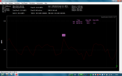
Resolution in Hz based on sampling frequency and FFT size. If you look, your spacing is 2.92 Hz (bin spacing I believe). So it won't be 350Hz exactly. You need to increase the FFT size or sampling size. Bin width is sampling frequency divided by FFT size. 48000/16384 = 2.929 So this means that every 2.929 is a bin or your resolution between frequency points is every 2.929 Hz.
Example: if your marker was on 50Hz (say it lined up perfectly), the next spot it would measure would be 52.929, then 55.858, and so on.
So the harmonic peak is close to 350, but your bin spacing lands it closer to 348Hz.
More experienced...correct me if I am wrong. If I am correct, I learned quite a bit over the last two years of focusing on FFTs and your information provided!
Dave
I found a tutorial from my dScope manu that details this exact problem and how to beat it. It's all in the bins and windows and the picket fence effect ;-)
You need to sit it out for 30mins but it's worth it:
Audio Test and Measurement Webinars page
Request the download and then they ask for some coordinates before you can download it.
Jan
You need to sit it out for 30mins but it's worth it:
Audio Test and Measurement Webinars page
Request the download and then they ask for some coordinates before you can download it.
Jan
My QA401 has just arrived in New Zealand - its a cool device and runs just fine from a Toshiba Kira laptop using a single usb port.
Measurement of phase is not 'right' though;
if I direct connect Left + out to Left + input it tells me there is -66 to -73 degrees, (should be 0)
if I direct connect Left + out to Left - input it tells me there is 106 to 114 degrees, (should be 180)
please excuse my lack of FFT based testing skill, I assume that this is a 'time' issue, but then I wonder why it is varying. Any suggestions?
New V1.481 QA401 software
I just discovered QA has a new 1.481 version of the software out that fixes a few things:
File Downloads
Sounds like one of the fixes may solve the phase computation problem loyaltolex posted.
I just discovered QA has a new 1.481 version of the software out that fixes a few things:
File Downloads
Sounds like one of the fixes may solve the phase computation problem loyaltolex posted.
Not a big deal, but one thing I did note when FR testing is the pulse on the "+" outputs is negative going.
Dave.
Dave.
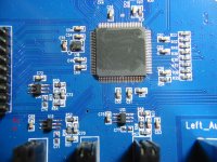
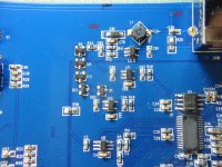
I managed to screw up my QA400 by discharging a 15000uF -40V capacitor through a ground loop, something like this: amplifier - input w a 25k pot turned to zero - QA400 input ground - QA400 USB con. - Computer GND - my grounded soldering iron touching the -40V . Lucky me only two IC-s burnt in it, a low dropout adj. reg. U13 and a boost converter U10 producing the +10V for the analog stages. The whole exercise cost me some nerve wrecking moments, because I don't have $550 for a QA401 and $60 for the parts from Digikey.😀
Attachments
I managed to screw up my QA400 by discharging a 15000uF -40V capacitor through a ground loop, something like this: amplifier - input w a 25k pot turned to zero - QA400 input ground - QA400 USB con. - Computer GND - my grounded soldering iron touching the -40V . Lucky me only two IC-s burnt in it, a low dropout adj. reg. U13 and a boost converter U10 producing the +10V for the analog stages. The whole exercise cost me some nerve wrecking moments, because I don't have $550 for a QA401 and $60 for the parts from Digikey.😀
I surprised this didn't shut down the USB power before any damage. A ground fault should have just burned some thin trace on the ground.
The damage doesn't come from the USB power, it come from the -40V. Once the U13 get shorted, the +5V USB shut down. The U13 low dropout reg. is directly connected to the USB power, the U10 boost converter has the L1 coil in series to the +5V.
From the HP-339 mod forum.... we used an external notch filter to atten the signal to the ADC for greater linearity in measurement apps. I found a passive notch filter (nill distortion) from B&K 1607. Then I got some help/suggestion on converting it to active for sharper notch width. I have it switchable -- active-passive mode.
Here is the before and after mod affect:


THx-RNMarsh
Here is the before and after mod affect:
THx-RNMarsh
Silence on the thread, everybody is on vacation.
Here's a little story how I used my QA400 in the last three years and also learned a lot by reading here how to use the QA correctly.
Many forum members disregarding THD measurements as not being relevant to sound quality.
I for one believing in meters, I'm not testing the mains with my tongue, why should I completely trust my ears?
The nice added distortions can foul one easily. So I compared CD players from the cheapest one to the pretty expensive one, from the first generation like the Hitachi DA1000 with a ceramic PCM53 from 1982 to the latest generations mega bucks Esoteric's and everything in between. For me it's easier to see the differences between them than hear it. The Redbook CD is pretty robust system, working well, like the FM radio. In my search I found what I was looking for, the best deal you can have on a player, to buy a 10-15 year old DVD player, those are shed by the owners in favor of the Blue ray ones.
Try the Pioneer DV-45, DV-47Ai or the Sony DVP-S9000es, fantastic players, with hard to beat specs.
An other subject comes up to time to time, that THD is done on a static signal, what music is not. I tried multi tones with
the QA400, like 6 or 12 tones, no numerical result, just visible one. I can see ca. 10dB rise of the noise floor going from 6
to 12 tones. Probably caused by IMD and the increased jitter. Up to this point for more realistic testing ,more music like
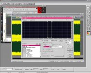
random signal is a noise with gap quite reviling, where anything in the bottom of the gap is distortion. Here's a picture of a
test on a ca. 20-23 years old Philips CD921 (TDA-1549 DAC) with the white noise with gap signal.
Here's a little story how I used my QA400 in the last three years and also learned a lot by reading here how to use the QA correctly.
Many forum members disregarding THD measurements as not being relevant to sound quality.
I for one believing in meters, I'm not testing the mains with my tongue, why should I completely trust my ears?
The nice added distortions can foul one easily. So I compared CD players from the cheapest one to the pretty expensive one, from the first generation like the Hitachi DA1000 with a ceramic PCM53 from 1982 to the latest generations mega bucks Esoteric's and everything in between. For me it's easier to see the differences between them than hear it. The Redbook CD is pretty robust system, working well, like the FM radio. In my search I found what I was looking for, the best deal you can have on a player, to buy a 10-15 year old DVD player, those are shed by the owners in favor of the Blue ray ones.
Try the Pioneer DV-45, DV-47Ai or the Sony DVP-S9000es, fantastic players, with hard to beat specs.
An other subject comes up to time to time, that THD is done on a static signal, what music is not. I tried multi tones with
the QA400, like 6 or 12 tones, no numerical result, just visible one. I can see ca. 10dB rise of the noise floor going from 6
to 12 tones. Probably caused by IMD and the increased jitter. Up to this point for more realistic testing ,more music like
random signal is a noise with gap quite reviling, where anything in the bottom of the gap is distortion. Here's a picture of a
test on a ca. 20-23 years old Philips CD921 (TDA-1549 DAC) with the white noise with gap signal.
Attachments

How did you generate that file with such a sharp transition to the silent band? I could use that trick.
- Home
- Design & Build
- Equipment & Tools
- QuantAsylum QA400 and QA401