... sounds even better 😀Wow! Your latest creation looks very good...
... sounds even better 😀
So, how much is the cost one channel?
who cares about money 😀
LC, thx for asking about progress on volume control. I ve done one pcb with the MDAC and one PCB for the front panel with 3 digits and IIR and encoder. Everything soldered, tested and programed (say 90%). Looks promising. unfortunatly, as usual their is one bug on each pcb so this remains a prototype, and my plan is to review the whole placement when I m back from vacation somewhere in august. So cant share more at that time, but if you are ok, I will send you the prototype mid august or so for you to qualify this MDAC.
lets keep the momentum !
Much more work compared to First One M since mosfets have to be matched whithin 1% or better, larger Mundorf present, bigger PCB, more SMD, .. overall more costs than expected. Thinking the price would set around 80-90% higer than M module, not decided yet.So, how much is the cost one channel?
Your idea to have volume control sitting on the top of input connector always on my mind, so yes please send me the prototype to review. We have very good equipment here to compare to.who cares about money 😀
LC, thx for asking about progress on volume control. I ve done one pcb with the MDAC and one PCB for the front panel with 3 digits and IIR and encoder. Everything soldered, tested and programed (say 90%). Looks promising. unfortunatly, as usual their is one bug on each pcb so this remains a prototype, and my plan is to review the whole placement when I m back from vacation somewhere in august. So cant share more at that time, but if you are ok, I will send you the prototype mid august or so for you to qualify this MDAC.
lets keep the momentum !
Never lost the momentum, not even for a second, on contrary last month First One L occupied me extensively, but managed to made a perfect module, stable as rock, powerful as horse and sounds great, so job done. Next on the list is First One S and of course all time present OEM work for a few companies.

Much more work compared to First One M since mosfets have to be matched whithin 1% or better, larger Mundorf present, bigger PCB, more SMD, .. overall more costs than expected. Thinking the price would set around 80-90% higer than M module, not decided yet.
Your idea to have volume control sitting on the top of input connector always on my mind, so yes please send me the prototype to review. We have very good equipment here to compare to.
Never lost the momentum, not even for a second, on contrary last month First One L occupied me extensively, but managed to made a perfect module, stable as rock, powerful as horse and sounds great, so job done. Next on the list is First One S and of course all time present OEM work for a few companies.
Looking forward to try them.
First One L Locked
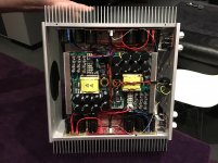
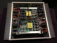
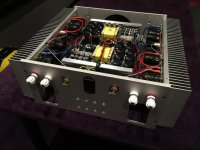
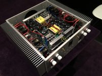
Now, after month of listening and testing First One L module in chassis bellow, I can confidently say this is the amp you'll hear and read about a lot. Back to work.. 😎
Looking forward to try them.
Now, after month of listening and testing First One L module in chassis bellow, I can confidently say this is the amp you'll hear and read about a lot. Back to work.. 😎
Attachments
Now, after month of listening and testing First One L module in chassis bellow, I can confidently say this is the amp you'll hear and read about a lot. Back to work.. 😎
Congratulations for a great looking (and probably performing) amp.
Did you find any inconvenient when passing the mains wires over the SMPS's transformer?
With that big enclosure, what is the T° of the fins?
Best wishes,
M.
Hi Lazy cat.
Looks really nice. What is the size of heatsinks you are using for the L first one 🙂
Sent from my ONE A2003 using Tapatalk
Looks really nice. What is the size of heatsinks you are using for the L first one 🙂
Sent from my ONE A2003 using Tapatalk
Yes it would too, Mundorf M-Lytic recommended.Hi LC ,would FO M benfit from more Capacity too ?
Regards DT
It's next on the list.Looking forward to First One S! Keep it up!
Best,
Anand.
Try it on +/-85 VCan not wait 🙂 Have the Chassis and parts of supply ready.
Prototype chassis, not mine, just for testing purposes. Mains wires will be routed differently in a production model, also DAC, USB, network renderer and preamp inside.Congratulations for a great looking (and probably performing) amp.
Did you find any inconvenient when passing the mains wires over the SMPS's transformer?
With that big enclosure, what is the T° of the fins?
Best wishes,
M.
It's Fischer heatsink, don't know the type, although big enough for FO L.Hi Lazy cat.
Looks really nice. What is the size of heatsinks you are using for the L first one 🙂
Sent from my ONE A2003 using Tapatalk
I've been following this project for some time now, and will definitely build myself FO-mono-amps in the near future. I really appreciate all the work that's been done here, and particularly that LC makes such a big effort to evaluate the sound for each iteration in addition to the excellent engineering.
I have a few questions, though, and would be grateful for any answers:
1) Will the Monolith monoblock chassis for the FO M be realized? I guess the project pipeline is rather full at the moment 🙂
2) Will a version of the FO M with extra Mundorf Mlytic capacitors be available, or do we just rig them in the obvious way as shown in the recent pictures?
3) The connection diagram shows GND on the PSU output connected to the chassis via a small circuit with MUR160 diodes.
- Can this connection between PSU and chassis be omitted?
- If not, will good 200V 3,5A diodes be sufficient instead of MUR160?
4) Will the FO S have the same gain as FO M 1.4 - i.e. around 27 dB?
Thanks! 🙂
Last edited:
Quote:
Hi LC ,would FO M benfit from more Capacity too ?
Regards DT
Yes it would too, Mundorf M-Lytic recommended.
Hi LC,
Could we please dig a bit further? How many electrolytics and what are the benefits re sound?
Are these benefits only applicable if using a lot of power on very dynamic passages or are there sonic benefits when using less than 70W?
Many thanks and well done again!
Claude
Really? It can get better?
Yes, details please. Will the additional cap boards I see with the L modules work with the M modules?
Also, now that I have over 100 hours of listening time on v1.4 M, should I re-calibrate the modules? If so, it is going to be hard to pull myself away from the sound of this awesome amp. 😉
I can see a L version build in the future for me, maybe not near future, but on the audio project list none the less.
Keep up the good work, Lazy. I think You have found your calling. Pretty soon, You can give up your day job!
Yes it would too, Mundorf M-Lytic recommended.
Yes, details please. Will the additional cap boards I see with the L modules work with the M modules?
Also, now that I have over 100 hours of listening time on v1.4 M, should I re-calibrate the modules? If so, it is going to be hard to pull myself away from the sound of this awesome amp. 😉
I can see a L version build in the future for me, maybe not near future, but on the audio project list none the less.
Keep up the good work, Lazy. I think You have found your calling. Pretty soon, You can give up your day job!
Clarification
Unless your day job is the First One Amp Projects. 😀
I figured I had better clarify, as your day job could be something You are passionate about also. The comment is coming from someone who is an Artist at heart (me), who works two jobs and runs a labor intensive, yet fulfilling Small business. 😛 I would Love to give up the jobs, keep the business and start another business more in line with my passion.
Either way, You have been an incredible inspiration, Lazy.
Pretty soon, You can give up your day job!
Unless your day job is the First One Amp Projects. 😀
I figured I had better clarify, as your day job could be something You are passionate about also. The comment is coming from someone who is an Artist at heart (me), who works two jobs and runs a labor intensive, yet fulfilling Small business. 😛 I would Love to give up the jobs, keep the business and start another business more in line with my passion.
Either way, You have been an incredible inspiration, Lazy.
stupid question perhaps...
This is maybe a stupid question but I am a bit doubting myself here and don't want to damage anything.
I am calibrating a pair of FO V1.3. I has been a while so I dogged up my old notes.
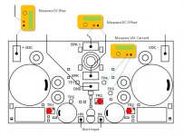
When I use the method as described in the picture I get negative readings for the 120mV and 280 mA. Off course I can swap the the leads on my DMM but I want to be sure...
So I anyone could tell me what is wrong and what is not.. that would be very reassuring..
This is maybe a stupid question but I am a bit doubting myself here and don't want to damage anything.
I am calibrating a pair of FO V1.3. I has been a while so I dogged up my old notes.
When I use the method as described in the picture I get negative readings for the 120mV and 280 mA. Off course I can swap the the leads on my DMM but I want to be sure...
So I anyone could tell me what is wrong and what is not.. that would be very reassuring..
Attachments
This is maybe a stupid question but I am a bit doubting myself here and don't want to damage anything.
I am calibrating a pair of FO V1.3. I has been a while so I dogged up my old notes.
When I use the method as described in the picture I get negative readings for the 120mV and 280 mA. Off course I can swap the the leads on my DMM but I want to be sure...
So I anyone could tell me what is wrong and what is not.. that would be very reassuring..
Speaker OUT must be connected to positive (+) multimeter lead as on photo. For VAS bias adjustment you just simply "turn around" multimeter leads to get positive current reading 🙂
The only stupid question is the one not asked...
I am sure v1.3 and v1.4 are the same in this regards. When I was measuring VAS bias (120mV for v1.3) between TP4 (+) and TP3 (-), I did indeed get a negative reading, as it is the negative side of the Amp. If You test between TP1 (+) and TP2 (-), You should get a positive reading.
I can not say why You are getting a negative DC bias reading on positive supply side. 😕 I do not know what PSU You are using. Do You get a positive DC voltage from the supply lead going to that terminal?
Correct for measuring the DC off-set.
I am hoping others will chime in also. I am thinking Lazy must really be getting close on figuring that L-version, as it has got very quiet here. 🙂
When I use the method as described in the picture I get negative readings for the 120mV and 280 mA. Off course I can swap the the leads on my DMM but I want to be sure...
I am sure v1.3 and v1.4 are the same in this regards. When I was measuring VAS bias (120mV for v1.3) between TP4 (+) and TP3 (-), I did indeed get a negative reading, as it is the negative side of the Amp. If You test between TP1 (+) and TP2 (-), You should get a positive reading.
I can not say why You are getting a negative DC bias reading on positive supply side. 😕 I do not know what PSU You are using. Do You get a positive DC voltage from the supply lead going to that terminal?
Speaker OUT must be connected to positive (+) multimeter lead as on photo.
Correct for measuring the DC off-set.
I am hoping others will chime in also. I am thinking Lazy must really be getting close on figuring that L-version, as it has got very quiet here. 🙂
- Home
- Vendor's Bazaar
- First One - mosFET amplifier module