Much better, the 1.4 a completely different amp.I am very curious of the sound from the new models though..
R.
With the 1.3 I was missing transparency, detail. The 1.4 has it all 🙂
Hi LC, congratulations for your new amp.
How many Mundorfs per rail is the ideal for the L version ?
Will it be better if we put more smaller caps like the ones in smps3k ?
How many Mundorfs per rail is the ideal for the L version ?
Will it be better if we put more smaller caps like the ones in smps3k ?
Last edited:
And possibly smaller quality caps in parallel, to bypass the bigger electrolytic ones?
Works great with linear PS, no clue on SMPS though...
Works great with linear PS, no clue on SMPS though...
Hi GbatokaiI've been following this project for some time now, and will definitely build myself FO-mono-amps in the near future. I really appreciate all the work that's been done here, and particularly that LC makes such a big effort to evaluate the sound for each iteration in addition to the excellent engineering.
I have a few questions, though, and would be grateful for any answers:
1) Will the Monolith monoblock chassis for the FO M be realized? I guess the project pipeline is rather full at the moment 🙂
2) Will a version of the FO M with extra Mundorf Mlytic capacitors be available, or do we just rig them in the obvious way as shown in the recent pictures?
3) The connection diagram shows GND on the PSU output connected to the chassis via a small circuit with MUR160 diodes.
- Can this connection between PSU and chassis be omitted?
- If not, will good 200V 3,5A diodes be sufficient instead of MUR160?
4) Will the FO S have the same gain as FO M 1.4 - i.e. around 27 dB?
Thanks! 🙂
I'm glad you find the First One project interesting for you, looking forward to see your end product. And now to the answers:
1. Yes, Monolith chassis is in final phase and will be offered here in second half of August. Chassis price per two monobloks will be around 200 EUR, prepared for First One M, SMPS1200A400 and DC sense. It will be possible to buy assembled Monolith amplifier too.
2. Yes, Cap Bank PCB on my PC screen at the moment, will suit two four-pin M-Lytic per rail, meaning two boards will be needed for one FO M or L module.
3. That was chassis connection diagram drawn for previous version. Please see attached First One M v1.4 User Manual where you can find actual chassis connecton diagram.
4. Yes, voltage gain will stay the same: Vout=24,4*Vin, ie. +27,75 dB
Best regards, L.C.

Hi ClaudeHi LC,
Could we please dig a bit further? How many electrolytics and what are the benefits re sound?
Are these benefits only applicable if using a lot of power on very dynamic passages or are there sonic benefits when using less than 70W?
Many thanks and well done again!
Claude
Kirchhoff's audio AC current loop includes/connects speaker, output transistors and PSU capacitance, so these caps have great influence to output current ie. sound quality, that's why they have to be quality ones. Sonic benefits are all over the spectrum and at low power too. 😉
Yes, details please. Will the additional cap boards I see with the L modules work with the M modules?
Also, now that I have over 100 hours of listening time on v1.4 M, should I re-calibrate the modules? If so, it is going to be hard to pull myself away from the sound of this awesome amp. 😉
I can see a L version build in the future for me, maybe not near future, but on the audio project list none the less.
Keep up the good work, Lazy. I think You have found your calling. Pretty soon, You can give up your day job!
I figured I had better clarify, as your day job could be something You are passionate about also. The comment is coming from someone who is an Artist at heart (me), who works two jobs and runs a labor intensive, yet fulfilling Small business. 😛 I would Love to give up the jobs, keep the business and start another business more in line with my passion.
Either way, You have been an incredible inspiration, Lazy.

Thank you very much Allen, you're too kind. 🙂
To the topic, yes these power cap banks will bring benefit to First One M as well.
After first 100 hours of playing time calibrations are not necessary to perform, anyway just check if output DC offset is within +/-10 mV limits, if not recalibrate the module's TR1, TR2. Complete module's bias current should be 280 mA, if not recalibrate TR3.
FO L will be interesting for the systems with big, power hungry speakers.
My primary job takes more time and is much more demanding, so no changover ahead in near future, although it's clear the man is successful when turns his hobby into bussines.
Best regards, L.C.
Glad you like it R. 😉Thanks for your replies... I successful calibrated the modules... And they sound perfect.
I am very curious of the sound from the new models though..
R.
FO L is even a little bit sonically ahead compared to M, as stated from our local audiophile society hehe

Much better, the 1.4 a completely different amp.
With the 1.3 I was missing transparency, detail. The 1.4 has it all 🙂

Hi LC, congratulations for your new amp.
How many Mundorfs per rail is the ideal for the L version ?
Will it be better if we put more smaller caps like the ones in smps3k ?
And possibly smaller quality caps in parallel, to bypass the bigger electrolytic ones?
Works great with linear PS, no clue on SMPS though...
Thanks Theodosis.
10 mF per rail (3 x 3,3 mF), not needed to be more than 3 pcs. per rail if they are as quality ones as Mundorfs are. Using bypass caps is a choice of personal taste, but please be careful not to bring resonance oscillations to PSU, using damping resistors in series will help a lot.
Attachments
Last edited:
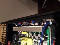
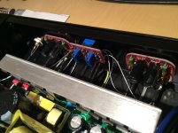
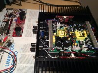
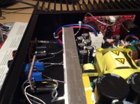
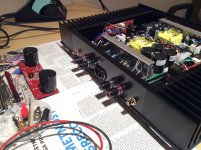
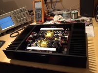
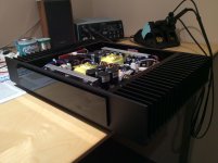
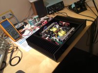
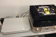
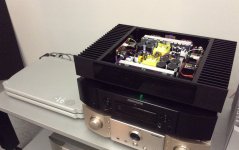
New First One M Black Mamba
Just made new Black Mamba for my friend. 😎
Just made new Black Mamba for my friend. 😎
Attachments
-
 IMG_0795.jpg369.1 KB · Views: 594
 -
 IMG_0798.jpg380.2 KB · Views: 582
 -
 IMG_0792.jpg537.5 KB · Views: 577
 -
 IMG_0794.jpg419.8 KB · Views: 567
 -
 IMG_0793.jpg550 KB · Views: 500
 -
 IMG_0790.jpg433.9 KB · Views: 249
 -
 IMG_0797.jpg346.2 KB · Views: 226
 -
 IMG_0791.jpg458.8 KB · Views: 235
 -
 IMG_0796.jpg424.5 KB · Views: 225
 -
 IMG_0799.jpg447.2 KB · Views: 223
Just made new Black Mamba for my friend. 😎
Cool build Andrej, and lucky friend! 🙂
Again many thanks for your kind and detailled reply LC, very appreciated.
It seems you have done again a great job, congrats!
"Regarding : FO L is even a little bit sonically ahead compared to M, as stated from our local audiophile society hehe"
Could it be that FO L works in class A for twice the power of FO M? Or are the sonic differences perhaps gain related (if different?)
Again congrats and many thanks for all your great efforts and sharings with the community
Claude
Just made new Black Mamba for my friend. 😎
Looks nice! Is that switch on the back of the amp for Bridge mode?
Hi LC,
Very nice build. Would First One L fit in the same chassis?
Sent from my ONE A2003 using Tapatalk
Very nice build. Would First One L fit in the same chassis?
Sent from my ONE A2003 using Tapatalk
Cool build Andrej, and lucky friend! 🙂
Thanks. Indeed. 🙂
Thanks Claude, I love my hobby and these are the results. 🙂Again many thanks for your kind and detailled reply LC, very appreciated.
It seems you have done again a great job, congrats!
"Regarding : FO L is even a little bit sonically ahead compared to M, as stated from our local audiophile society hehe"
Could it be that FO L works in class A for twice the power of FO M? Or are the sonic differences perhaps gain related (if different?)
Again congrats and many thanks for all your great efforts and sharings with the community
Claude
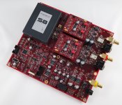
There are some differences between M and L module so perhaps SQ differentiate because of that. More parts, new PCB layout, higher power in Class A, etc., did not find time yet to determine the cause, surely sum of all little things brings the sound to another level. OLG and CLG are nearly the same.
Fred, the switch on the back panel has three positions and it serves to set VU-meter's activity-range:Looks nice! Is that switch on the back of the amp for Bridge mode?
OFF, -10 dB, 0 dB
Yes it would fit, but with half the bias set through output mosfets.Hi LC,
Very nice build. Would First One L fit in the same chassis?
Many thanks again for your reply LC 🙂
If gain is the same and sound is improved, me says even people looking for low power application could then benefit from the FO L... regardless the power needs 🙂
Well done again LC!
Claude
If gain is the same and sound is improved, me says even people looking for low power application could then benefit from the FO L... regardless the power needs 🙂
Well done again LC!
Claude
Andrej,
I've just checked VAS current biasing and I have about 280mV on one board and 250mV on the other and amp is on 24h/7d. It's a little higher than expected (180mV) but then again I think it wouldn't hurt much. I didn't check output transistor bias current but I feel it's a little warmer than previous V1.2 on the same power supplies(Hypex).
FO is directly coupled(no cap) to SEN I/U converter because I didn't finish preamp yet, so output DC is little bit off during first minute or two and then it's settles from 70 mV to about 10-20 mV.
Hi miksi
It is ideal to set VAS and output bias when amp is settled to operational temperature, since both of your readings are too high, please recalibrate and set them to recommended values. First One doesn't have DC servo meaning, going from cold start to operational conditions, output DC offset starts from -70 to +/-10 mV, that's completely normal behaviour. Heatsink's operational temperature should be 42-44 C, of course without input signal present.
Pleased with SQ of v1.4 compared to v1.2? Drives your speakers well?

LC,
Is this your own DAC design? If yes, will it be something we can DIY or commercial product? Could you share a little details?
If not something you've made, what brand/model is it?
Thanks
Do
Is this your own DAC design? If yes, will it be something we can DIY or commercial product? Could you share a little details?
If not something you've made, what brand/model is it?
Thanks
Do
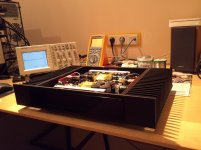
Analog DAC is MSB product, 384 kHz discrete Ladder DAC. This one on pic is the latest version, full option package with Network Renderer, Quad USB, analog input, volume control, separate PSU. I have it for FO testing purposes and it is by far best DAC I ever had.
Besides also having DAC on pic attached, but it still needs some upgrade work to be done to come even close to.
Analog DAC enabled me making FO L sounding even better than expected, every little tweak could be evaluated with ease. Very happy with the 'tools' available. 🙂
Besides also having DAC on pic attached, but it still needs some upgrade work to be done to come even close to.
Analog DAC enabled me making FO L sounding even better than expected, every little tweak could be evaluated with ease. Very happy with the 'tools' available. 🙂
Attachments
LC,
Is this your own DAC design? If yes, will it be something we can DIY or commercial product? Could you share a little details?
If not something you've made, what brand/model is it?
Thanks
Do
Salut Do,
La Voila-> List Prices
Anand.
Hmmm. cheap DAC... I thought you wouldn't settle for only the Select DAC @ 90K 😉 LOL!
Jokes aside, it seems like a super nice DAC! Me wants!
Do
Jokes aside, it seems like a super nice DAC! Me wants!
Do
The soekris dam 1021 is a ladder dac to, same "type" as msb
DIY Line - dam1021 - Audio Products - Products
DIY Line - dam1021 - Audio Products - Products
The soekris dam 1021 is a ladder dac to, same "type" as msb
DIY Line - dam1021 - Audio Products - Products
I'm sure it is a very good DAC but the filters selection is probably too much for many of us... Just too many filters, it would be great to have a default high quality filter like the msb. Maybe msb goes even a step further by selecting automatically an appropriate filter according to the source type and sampling rate?
Do
- Home
- Vendor's Bazaar
- First One - mosFET amplifier module