Hi,
@1714: "...the 861 ticks all the right boxes for use with TDA1541 ..., but as it's hi-z output, a buffer is required on the output I think."
The OPA 861 is like the AD844 wo. the Buffer and specced for only +-5V supplies.
The former OPA860 included a buffer.
TI speccs the output impedance of the OPA861 as 54kOhm||2pF.
The input impedance varies between 6R7 and 12R5 depending on the chosen idle current.
This is considerably lower than the 50R of the AD844 input.
The low-impedance input node and the high-impedance output node can both sink and source up to +-10mA of current.
The DS Rev.F of the AD844 doesn´t specc these important values for the current conveyor part alone, but on p14/20 it says: "The current available to charge the capacitance (about 4.5 pF) at the TZ node is ...... In practice, the input current eventually causes the mirrors to saturate. When using ±15 V supplies, this occurs at about 10 mA (or ±2200 V/μs)."
The current compliance at the TZ-node seems to be +-5mA, according to Fig.42 and associated text.
This figure implies that stacking shouldn´t be needed with a TDA1541, if it weren´t for the lower input impedance.
But then, all figures in the DS relate to a closed loop buffer-included mode. 🙄
jauu
Calvin
btw. the OPA861s voltage noise figures indicate its suitability also for a phono-innput stage - only current noise figures and 1/f freq are a bit high.
Hi, yes the 844 DS isn't very implicit at all
More questions,
1. Does a current conveyor behave like a valve in terms of saturation? (overdriven creates 2nd order harmonics)
2. What is the purpose of the second 861 in the AYAII, dedicated buffer perhaps?
3. Is 2658 direct replacement for LF353 VFB in socket? Both are Dual-Dip-8.
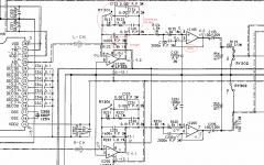
Dual or single regardless, if one used the existing circuits that follow a TDA, i.e. the I/V etc... In attached schematic there is the usual feedback around 1st stage but there are other resistors in series. With CFB, a specified RFB resistor is required for optimal performance. Can one swap the resistor, or does attention have to be paid to the combined resistance around entire set of components (De-emp EQ etc).
Further along, there are also relay's in the signal path, I seen mentioned they are detriment to sound.
More questions,
1. Does a current conveyor behave like a valve in terms of saturation? (overdriven creates 2nd order harmonics)
2. What is the purpose of the second 861 in the AYAII, dedicated buffer perhaps?
3. Is 2658 direct replacement for LF353 VFB in socket? Both are Dual-Dip-8.
Dual or single regardless, if one used the existing circuits that follow a TDA, i.e. the I/V etc... In attached schematic there is the usual feedback around 1st stage but there are other resistors in series. With CFB, a specified RFB resistor is required for optimal performance. Can one swap the resistor, or does attention have to be paid to the combined resistance around entire set of components (De-emp EQ etc).
Further along, there are also relay's in the signal path, I seen mentioned they are detriment to sound.
Attachments
Last edited:
Hi,
1) tubes generate more higher harmonics than just k2.
The nice thing about DACs is that the maxmum output is well defined, so that saturation of the following stages can be avoided under all circumstances.
2) Yes
3) No, the LF353 s a rather slow voltage feedback OPA, the OPA2568 a fast current feedback OPA.
jauu
Calvin
Hi,
1) tubes generate more higher harmonics than just k2.
The nice thing about DACs is that the maxmum output is well defined, so that saturation of the following stages can be avoided under all circumstances.
2) Yes
3) No, the LF353 s a rather slow voltage feedback OPA, the OPA2568 a fast current feedback OPA.
jauu
Calvin
Hi Calvin, I've just had a bit of a look at your site, and the (cascoded) hybrid-Darlington buffer A(CCS) buffer interests me, do you sell it or have commissioned someone else to make it (kit or whatever??
Cheers George
Hi,
I don´t sell or have commissioned someone else to do so.
So far I even don´t know if anyone has built and tested the thing 😉
The simulated circuits in Fig.2 are designed with SMD parts for which throughhole alternatives exist.
Due to the requirement of the JFETs gate-source-voltage needing to exceed the Vbe of the bipolar booster the choice of JFETs is limited, excluding the ´audio-marked´ ones.
JFETs with suffciently large Vgs are rather intended for switching purposes.
The hybrid-compound super buffer, or Calvin-Buffer requires the same effort regarding parts number count, but has proven its qualities.
With that buffer You can choose the SK170/389, BF862 and similar audio-related JFETs too as the Vgs limitation doesn´t apply.
You can also omit with the cascoding JFETs, with the advantage of lower parts number count/cost and higher clipping treshold.
Due to the headroom the cascoding JFETs eat away, the non-cascoded Version could be supplied with ~4-5V lower supplies for the same undistorted output voltage.
The differences to the cascoded version are just increased heat power loss in the remaining master JFETs, a little higher THD into very low impedace loads, and higher undistorted output level for the same supply line voltages.
There have been layouts for both the throughhole and SMD version.
(just search for Calvin-Buffer in general or in particular in the Paradise-Phono thread, or in my thread "Preamp-Buffers - simple idea").
But its that simple that You could solder it Bug-style or on a perforated board.
jauu
Calvin
Last edited:
What about deliberately over driving current mirror/conveyor section for non-linear result, like is possible with tube?Hi,
tubes generate more higher harmonics than just k2.
The nice thing about DACs is that the maxmum output is well defined, so that saturation of the following stages can be avoided under all circumstances.
CFB have slightly more in common with tube, than a VFB does ...
Alot of that cascoded page is way over my head, for now.
Much prefer IC solution though, baby steps... What are your experiences in relative performance between your simulation versus IC?
Hi,
deliberately driving into clipping is no HiFi after my understanding ... rather a electronic Brexit 😉 ... not my cup of tea.
The Calvin Buffer has proven to be verylow THD in simu and praxis.
A OPAmp couldn't do better in this regard.
Its just easier to implement and cheaper.
Sonically I prefer the simple discrete stages as to my ears they let music be music, while the globally fed back OPAmps sound like a reproduction, a conserve, artificial ... not my cup of tea also.
But then ... other ears different tastes 😉
jauu
Calvin
BUT the data sheet reads "output stage has been optimized to drive low resistive loads" Does this statement necessarily mean it's high-z output?
It normally means that it can source appreciable current to drive the low impedance load. It doesn't say anything about it's Zout. With the buffer and feedback, Zout is very, very low.
The 'open loop trans-impedance' of the 2658 is 180kohm. Which I think translates to "you well need a buffer unless your power amp has input impedance of more than this value".
The OL transimpedance is the impedance seen at the internal compensation cap node and is not accessible from the outside in this chip (in contrast with the AD844 wehre this 'Tz' node is accessible).
The transimpedance is important for the open loop gain but not for Zout (which, again, is low due to the output buffer and feedback, if used).
Jan
Thanks George!
Hi George, Just wanted to thank you for this thread and your PCM1704 dac work. It gave me the desire to build my own. I am so happy with the results even if I went a little rouge on my implementation. I am as they say a "Happy Camper". 😀
Hi George, Just wanted to thank you for this thread and your PCM1704 dac work. It gave me the desire to build my own. I am so happy with the results even if I went a little rouge on my implementation. I am as they say a "Happy Camper". 😀
Thanks jan for clearing those confusions.
Calvin, but is the distortion solid state like or tube like?
I considered putting tube pre-amp somewhere but if solid state can do it why not (doubt it - would like to clarify CFB though).
Brexit - I didn't vote - No stake in it when I can DIY my way out. heh. 😀
@ forum, in applications where DF is omitted, is it generally better to utilize CFB with externalized Tz, than one without?
In other words can all CFB buffer withstand imaging provided within 'bandwidth' spec or do they perform worse than 844 in all cases...
Last edited:
Hi,
is there such a thing as ´tube-like´ or ´solidstate-like´ distortion?
I don´t think so.
THD is related to many parameters, like shape of transfer function curves, bias points etc, etc, and of course circuit design.
The role of Vac or Sand in this game is certainly minimal, and about which I wouldn´t worry at all.
jauu
Calvin
M3 Parallel DAC with tube
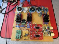
Hi giro, I kind of wonder what your chasing here. Tube stages are known to give richness to digital sound. An example of that is my M3 prototype. I wonder if in a sense your chasing tone. Speaking as a guitar player, every player I have ever met was chasing a particular sound. I recently pulled the M3 back into play. My interest is in finishing it someday soon. So... What does it sound like? Well I really like it's smooth play back. It has the smooth quality of the triple stack AD844 + Buffer. In fact I was a little surprised by that. The M4 (1704 + DDNF+ OPA627) has a very different sound. M2 and M4 share the commonality of the DDNF stage. So they have the same basic tone if you will. The M3 has a parallel TDA1541A S1 crowns into a simple resistor I/V (25 Ohms). The tube stage is based on a 6N27P tube in SRPP with a 2SK170 from a Swedish DIY thread. Nothing is running in saturation, plenty of head room. Yet the tube circuit is rich and enjoyable. Really sings on guitar solos. My point is you get pretty close with the triple stack AD844 + BUF03 in my case. So it is possible to get a similar sound as the tube although not it's equal. 😀Thanks jan for clearing those confusions.
Calvin, but is the distortion solid state like or tube like?
I considered putting tube pre-amp somewhere but if solid state can do it why not (doubt it - would like to clarify CFB though).
Brexit - I didn't vote - No stake in it when I can DIY my way out. heh. 😀
@ forum, in applications where DF is omitted, is it generally better to utilize CFB with externalized Tz, than one without?
In other words can all CFB buffer withstand imaging provided within 'bandwidth' spec or do they perform worse than 844 in all cases...
Attachments
Perhaps 2nd harmonic dominated or 3rd harmonic dominated distortion???Hi,
is there such a thing as ´tube-like´ or ´solidstate-like´ distortion?
I don´t think so.
 and not a dime more....
Hi,
different tubes distort differently, a triode differs from a pentode.
A Bipolar differs from a JFET, differs from a MOSFET.
But still circuit design dominates the harmonic distribution and level overall.
When Torchwood tells from richer sound with his tube equipped DAC, can he -or anyone else- be sure that this listening impression is not due to the different DAC output configuration, as DACs feeding into a resistor generate a different and higher-in-level distortion spectrum than DACs feeding into a (virtual) short?
Can we be sure that not already the knowledge of a tube working somewhere in the circuit triggers our Placebo listening (on a subconscious level)?
How about the omittance or application of feedback loops encompassing multiple circuit stages?
It opens a whole can of worms, as unfortunately most postulated variations of sonic fingerprints are just non-valid claims, viewed from a technical or scientific standpoint.
Say You'd double a single-ended buffer with dominating even order harmonics and configurate them as a balanced output (probabely the change with the lowest number of varied parameters of all).
The harmonic distribution and THD-level will alter drastically.
The even harmonics would mostly cancel leaving the odd harmonics dominant.
After popular thinking about the sonic influence of even and odd harmonics, the balanced circuit -in fact all balanced circuits- should sound terrible.
Praxis and even common sense tells us different, heck even most will probabely prefer the balanced output.
In other words ... don't put too much money...... 😉
jauu
Calvin
Hi Guys
What torchwood is doing is only to share his experience with the mods
that he has done . What you guys should be doing instead is to pick up
the initial part from Georgi & Torchwood & do you own experiment & not
speculating or debating. If I were to tell you how I tweak my system to
how I like it, proberly you guys will be flaming me n saying it's hogwash but
I don't give a **** cause it works for me. Morale of this is DiYaudio is a
wonderful forum to learn from. here on one should branch out on our own
audio adventure.
I agree. the experiences of George and Torchwood are a powerful inspiration to try for themselves what 'suggested in this thread with very interesting and instructive contributions of other users. I'm trying to build my new creature ... another DAC based on these experiences
Hi Guys
What torchwood is doing is only to share his experience with the mods
that he has done . What you guys should be doing instead is to pick up
the initial part from Georgi & Torchwood & do you own experiment & not
speculating or debating. If I were to tell you how I tweak my system to
how I like it, proberly you guys will be flaming me n saying it's hogwash but
I don't give a **** cause it works for me. Morale of this is DiYaudio is a
wonderful forum to learn from. here on one should branch out on our own
audio adventure.
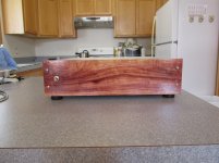
Looks great!Finished the dac today. Used a gloss finish on the African Paduk. Beautiful grain and color. Nice to be done. Can move on to the other prototype the M3. 😉
Myself, I planned this week to alter the TDA1541A S1 setup of my CD player. No too exclusive parts, but a nice AD826 for each channel, along with some other mods collected from this forum.
Last edited:
Resistor I/V
In my experience, the I/V resistor is critical. ECDesigns championed the Moebius resistor and hand wound them in a non-inductive manor. The next best that I could find was the Rhopoint Econistors. That is what I used in the M3. Making my own non-inductive resistors is not something I would attempt. I'd love to see someone do a study of I/V's with test results. I don't have a device for spectrum analysis or a distortion meter to attempt that. So all I can do is use my ears. Thus expressing an opinion based on what is available to me.
In my experience, the I/V resistor is critical. ECDesigns championed the Moebius resistor and hand wound them in a non-inductive manor. The next best that I could find was the Rhopoint Econistors. That is what I used in the M3. Making my own non-inductive resistors is not something I would attempt. I'd love to see someone do a study of I/V's with test results. I don't have a device for spectrum analysis or a distortion meter to attempt that. So all I can do is use my ears. Thus expressing an opinion based on what is available to me.
Upgrade

Hi esgigt, Keep us posted on your progress. DIY can be a very enjoyable hobby. I have learned a lot in the 20 years I have dabbled with CD playback and audio.Looks great!
Myself, I planned this week to alter the TDA1541A S1 setup of my CD player. No too exclusive parts, but a nice AD826 for each channel, along with some other mods collected from this forum.
- Home
- Source & Line
- Digital Line Level
- Using the AD844 as an I/V