Fine! Twist my arm! 🙂
There appears to be a fair number of people who have LM4780s sitting in desk drawers collecting dust and several of these people have asked me to make another board run. I have started a group buy thread for the Parallel-86: http://www.diyaudio.com/forums/group-buys/293914-neurochrome-parallel-86-group-buy.html#post4767811
If there is enough interest and, more importantly, enough people who are willing to put money down, I will make one final board run.
If you're interested in Parallel-86 boards and can put money down by early August, please indicate your interest on the Group Buy thread.
Tom
Last edited:
RS = Allied in North America. They have stock in the UK (and New Zealand or Australia from what I hear) but no stock in the US or Canada.
I didn't check RS as they don't show up in TI's list of distributor stock. It's good to know that not just Newark/Farnell is sitting on stock.
Tom
I didn't check RS as they don't show up in TI's list of distributor stock. It's good to know that not just Newark/Farnell is sitting on stock.
Tom
Fine! Twist my arm! 🙂
If there is enough interest and, more importantly, enough people who are willing to put money down, I will make one final board run.
If you're interested in Parallel-86 boards and can put money down by early August, please indicate your interest on the Group Buy thread.
Tom
I love the sound of my Mod86. However I have a pair of B&W N803s in a 16'W X 26'L x 9'H room. The speakers are 3 3/4' out from the 16' front wall and 3' away from the side walls. I recall recommended power is 50 to 250 Watts. While sensitivity is 90dB and it is considered an 8oHm speaker it does drop to 3oHms
I think the Mod86 might be pushing its limits with large scale symphonic pieces during loud full orchestral passages.
Also, in the smaller room, I sit about 7' away from the speakers. I sit about 12' away in the larger room.
How many PCBs make up a parallel-86. For example is the a power PCB similar to the Power-86? Is there a diagram or picture of the layout, similar to ones in the Power-86 and Mod86 documentation? Does it require a larger transformer than the Mod86?
Thanks,
henrylrjr
Is the amp clipping or just not loud enough. If it's not clipping (distorting) at full volume, you need a bit more gain in the preamp.
The Parallel-86 is a completely different PCB. It uses the LM4780 IC which Texas Instruments decided to discontinue late last year. There is very limited distributor stock available - none of it in North America! Even if the group buy happens, I cannot provide assembled boards for the Parallel-86 as I can't guarantee that I can get the ICs.
I will have some higher powered amps available this fall. Stay tuned.
Tom
I drilled a two diameter hole for the LED in the 3/8" thick aluminum face. No glue or silicone needed since it's a light press fit. Everything was easily and accurately done via my machine shop equipment and all the tools.
I'm thinking of screwing the aluminum, finned, 5.6Kohm resistor to the faceplate with some thermal grease on the back of the resistor. I would think the large faceplate would help dissapte some heat even though it has no fins.
I would also think that 24awg copper wire (I happen to have some left over) would be sufficient from the resistor to the led cathode and from the led anode to ground since they will only carry about 2 VDC. Another question is can the LED cathode and anode wires be bent, with a good sized radius, to make for a neater install?
Does all this make sense?
Thanks,
henrylrjr
Last edited:
Finishing up
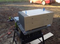
Finally things have settled down, and the weather is good enough to be in the shop.
The original plan was for a six channel Mod86, but I switched speakers to LX-MINI's (love them BTW). I only need 4 channels now. That's the reason the heatsinks are oversize. I think it looks cool though.
Myself, I like the look of wood gear, I think it's classy. I line the inside of the box with thick aluminum sheets for safety (PE).
Here's the chassis I made. Just need to do some wiring now.
Can't wait to be rid of my big-box-store crapo receiver. Soon
Attachments
Alex,
Nice work. You might as well sell your receiver now! Tom's designs mean business!
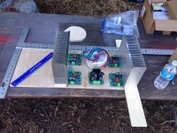
Regarding your PS, I hope 20,000 uf per rail (from what I can see in your pic) is enough for 4 boards...
Best,
Anand.
Nice work. You might as well sell your receiver now! Tom's designs mean business!
Regarding your PS, I hope 20,000 uf per rail (from what I can see in your pic) is enough for 4 boards...
Best,
Anand.
I'm thinking of screwing the aluminum, finned, 5.6Kohm resistor to the faceplate with some thermal grease on the back of the resistor. I would think the large faceplate would help dissapte some heat even though it has no fins.
A couple of blind tapped holes into the back side of the thick front panel would work perfectly for attaching the resistor.
I would also think that 24awg copper wire (I happen to have some left over) would be sufficient [...]
I agree.
Another question is can the LED cathode and anode wires be bent, with a good sized radius, to make for a neater install?
I prefer to cut them to 5-6 mm from the LED body so they don't bend. I'm always a bit concerned with metal fatigue. I then solder stranded wire (20 AWG, though thinner wire will work just as well) to the leads and seal the deal with heat shrink tubing.
Nice work. You might as well sell your receiver now! Tom's designs mean business!
🙂
Regarding your PS, I hope 20,000 uf per rail (from what I can see in your pic) is enough for 4 boards...
For a four channel amp used for bi-amping, such as for use with the LXmini, one Power-86 with the default 2 x 22000 uF is plenty.
In case of more power hungry low-impedance speakers, such as the SL Orion or LX521.4, I suggest no more than two MOD86 boards per Power-86.
Tom
The original plan was for a six channel Mod86, but I switched speakers to LX-MINI's (love them BTW). I only need 4 channels now. That's the reason the heatsinks are oversize. I think it looks cool though.
Myself, I like the look of wood gear, I think it's classy. I line the inside of the box with thick aluminum sheets for safety (PE).
I like it. It looks like an amp that means serious business. That seems fitting for the performance level. 😀
Tom
@nysavsr. Thanks for the compliment. I had the same concern a year ago when planning. But then I saw that Tom personally built a couple of 4 channel Mod86 for lxmini successfully with only 1 power86. I wish I could remember where the pics are, it's beautiful.
@Tom. Glad you like it! Standing in your shoulders man. Putting the board together seemed a lot like paint-by-number to me. Thanks for everything Tom.
@olaru. I found at a local hardware a tap n die kit. I hate buying cheap tools, but don't like spending a fortune either. The Dewalt kit of Metric tap n die I got comes with drill bits, and a chart showing which drill bit size to use with each tap. IIRC the Dewalt kit was around $40. Easy to find much cheaper taps, but I didn't have to break the bank to get a decent one that will last some years.
I'm using M5 bolts for metal corner (L) brackets to hold the chassis together. M3-.5 x 6mm to hold the LM3886 chip against the heat sink, with thermal grease of corse.
Just an ordinar hand drill with variable speed to make the holes (go slow), then a little oil on the end of the tap and slowly turn the tap by hand in the hole to cut the threads. I just take my time with it, and though the aluminum is soft and easy to cut, I have broken a drill bit years ago because I was going too fast. It was easy.
A couple of blind tapped holes into the back side of the thick front panel would work perfectly for attaching the resistor.
I prefer to cut them to 5-6 mm from the LED body so they don't bend. I'm always a bit concerned with metal fatigue. I then solder stranded wire (20 AWG, though thinner wire will work just as well) to the leads and seal the deal with heat shrink tubing.
Tom
I made the blind tapped holes last night. I feel the same about metal fatigue, and micro cracks, that bending usually causes. I positioned things such that the LED leads don't need bending or trimming but think trimming is a good idea that will minimize bending/drooping over time. I had planned to use heat shrink tubing. The leads are so close to each other it seems like a short waiting to happen.
I found at a local hardware a tap n die kit. I hate buying cheap tools, but don't like spending a fortune either. The Dewalt kit of Metric tap n die I got comes with drill bits, and a chart showing which drill bit size to use with each tap. IIRC the Dewalt kit was around $40. Easy to find much cheaper taps, but I didn't have to break the bank to get a decent one that will last some years.
McMaster-Carr has an amazing selection of taps. I bought some really nice TiN coated (that yellow stuff) spiral flute bottom taps there for M3 and M4 threads.
Metric threads are easy: (Drill diameter) = (Thread size) - (Thread pitch).
M3x0.5 for example requires a 3-0.5 = 2.5 mm hole. Rather than punching through with the 2.5 mm drill bit first, I recommend drilling a 2.0 mm hole first. Then 2.5 mm. Not only will it be much easier to get the hole in the right spot, it will also result in a hole that's closer in diameter to the diameter specified on the drill bit. If I had a 2.3 mm drill bit, I'd probably go 2.0 - 2.3 - 2.5mm. Then again, it's not like we're building a space shuttle here.
A tapping block is worth its weight in gold (even at today's gold prices). I made my own from a chunk of aluminum that I drilled holes through using a drill press. Make the holes large enough that you can get the tap through but not much larger. A tapping block makes it so much easier to get the threads perpendicular to the workpiece.
Cutting oil is a must. I don't think I've broken a tap since I started using cutting fluid (knock on wood!) I use A-9 – not to be confused with A-1 steak sauce. I don't think A-1 works for cutting aluminum and A-9 tastes awful! 🙂
Tom
The wonders of spring steel. Aavid P/N: MAX08NG (available at Mouser). A thin coat of Wakefield 120 thermal grease on the back of the LM3886, digitally distributed (i.e. spread with a finger). Clamp positioned to put pressure roughly on the middle of the fat part of the LM3886TF package. I get 45 W (8 Ω) and 80 W (4 Ω) with ±30 V supplies.
The image shows the position of the clamp on my new LM3886DR amp.
Tom
The image shows the position of the clamp on my new LM3886DR amp.
Tom
Attachments
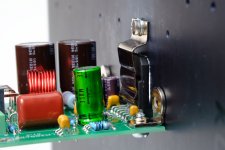
The wonders of spring steel. Aavid P/N: MAX08NG (available at Mouser). A thin coat of Wakefield 120 thermal grease on the back of the LM3886, digitally distributed (i.e. spread with a finger). Clamp positioned to put pressure roughly on the middle of the fat part of the LM3886TF package. I get 45 W (8 Ω) and 80 W (4 Ω) with ±30 V supplies.
The image shows the position of the clamp on my new LM3886DR amp.
Tom
Those clips definitely look worth a try, a nice way for the average DIY 'er to avoid the pitfalls of the screw-through-tab technique. Out of curiosity I checked DigiKey and they stock them also.
Mike
That looks cool. Super convenient for a test bench I imagine, but I'm not a designer, so that's just a guess.The wonders of spring steel. Aavid P/N: MAX08NG (available at Mouser). A thin coat of Wakefield 120 thermal grease on the back of the LM3886, digitally distributed (i.e. spread with a finger). Clamp positioned to put pressure roughly on the middle of the fat part of the LM3886TF package. I get 45 W (8 Ω) and 80 W (4 Ω) with ±30 V supplies.
The image shows the position of the clamp on my new LM3886DR amp.
Tom
I really like those little L-bracket things holding the pcb to the heatsinks.
If I had a 2.3 mm drill bit, I'd probably go 2.0 - 2.3 - 2.5mm.
Tom
Tom,
2.0 to 2.5 is a very appropriate and methodical 0.020" (apologies to you metriphiles) step-up from the pilot. If we need to split that into two ~0.010" steps I'm afraid we're drifting back into the extended bout of OCDiy/ADHDiy from which this thread has only recently emerged. Remember, the perfect is the enemy of the good!
That looks cool. Super convenient for a test bench I imagine, but I'm not a designer, so that's just a guess.
The clips are easier both for testers and builders. The hole placement for the mounting screw is nowhere near as critical with the clip as it is when you use the mounting hole in the LM3886. The clip also ensures a good clamping pressure all across the LM3886 package. As long as the LM3886 is mounted perpendicular to the PCB, the clips also make it possible to solder the IC to the board, drop the board into the enclosure, tighten the mounting screw on the clip and be done. That's much easier than the dry-fit, solder, disassemble, apply thermal grease, reassemble process I've recommended until now.
I really like those little L-bracket things holding the pcb to the heatsinks.
I do too. They're a little cumbersome in the PCB layout process as they do need to align precisely with the back of the LM3886, but they are so much easier for the builder to deal with.
Tom
- Home
- Amplifiers
- Chip Amps
- Modulus-86 build thread