Now to see even further how the dims of the cilinders influence the overall frecv i shrinked the cilinders and measured 5 times each at 5 mins distancejust to be shure.
Now you know i told you that i had 34cm@ 51.5 cm hight on the first ruban@4.5cm per half cilinder ; in these measurements i measured in the originall state (dims) and then shrinked at -1cm from each syde making a sheet for one cilinder 32cm@3.5cm per half cil and then -2cm pe syde making the sheet for each cilinder 30cm@3cm per half cil.
Be aware!!! these measurements are valid only for this type of foil and maybe for a foil with paper on one syde; on my paper versions the results where totally reversed.
As you can see the shrinking the cilinders is causing the dips to be deeper so its worsening things up. As i sayed 34cm@51.5or 51cm for the 50cm ruban is optimum.
Subjectivelly speaking on the original version everithing sounds good, then shrinking the cils with -1cm@@3.5cm/half@32cm per sheet, makes the lower voice (bass voice) abit thinner but its no problem since it would not go down there when coupled with a woofer and this seems to be the limit (smallest cilinder diam possible without affecting the overall performance for foil and i suspect the same in the paper versions), BUT when shrinking further at -2cm@3cm/half@30cm, subjectivelly speaking, the overall sound seems restrained, and here i mean lows, mids, and hights.
To me the best was leaving the originall dims as they are at 34@51cm (i trimmed abit the hight for better verticall centering) .
Cheers
Sergiu
PS: the "4 cm @32cm per sheet -1CM" from the measurements (blue) is playing in full range..
Attachments


Last edited:
So lets refresh the list abit.
SOME MORE HINTS. I will write them down because later i will forget..):
1. The magnets:
*Should they be bigger or smaller in lenght?
Smaller could be costly to achieve the same strenght, but longer could be cheaper if they achieve the same force togheter.
*should they be taller or thinner?
NA (i dont have funds for buying magnets again)
*should they be weaker or stronger?
Stronger it will ad some dB but if the cilinders are not proprely damped and designed those dB's could drive you insane because of the nasty resonances amplified. Also stronger magnets will add dollars in plus to the metal plates (more thicker,or other steel ads more money to the count).
2. Metal plates:
*A very important thing that nobody answered yet: should the plates be 2cm+1cm width so that the flux would be more concentrated or other dimensions like 2+2cm would be also good?
I use the second solution with 2+2cm width because i seen that Wrine's 3cm version bended at 3mm gap. Normally the gap is 4mm, but because i used bigger plates i got 3mm gap without bending.
*what material to use for the plates?
A37 french steel was used in the original design.
AISI 1018 was also used with succes.
Romanian equivallent is OLC15X.
We use colld rolled steel now with succes and i think that with weakened magnets like n42,n38 standard AISI1017, AISI 1018 steel can be used also.
It seems that a larger quantity of carbon diminishez the force and lesser carbon improves force further but saturates more easier. So it must be just as its needed, not too much nore too little quantity of carbon.
3. The gap:
*2,3 or 4mm?
4mm for n48 magnets its perfect, smaller gap could bend the steel..
3mm ads some dB and its the limit of suportability because you can barely keep the coil centered, and as it is the coil could bend from humidity and rub on the plates causing distorsions easily and eventually take the output trannies to their graves as they did to mine .
2mm doesnt add to much stuff, its very hard to center and keep centered the coil. Also if the coil bends only a little bit disaster will strike.
Here we have also a testimony from our colleague tubegeek974:
"PS i use neo magnets from china and 3mm gap on one loudspeaker then tryied 2MM on the other with not mutch more improvements in efficiency but lots of sorrows for centering the bobin!"
4. The coil:
*single sided or double sided?
DOUBLE SIDED FOR SHURE (its the best till now from all the measurements).
SERIES OR PARALEL?
Series its best with +-+- conected and then conected in reverse (best from measurements) .
Altought the series coil measured better than parallel i chose the parallel version in antiphase even for my final setup (when i will finish it) because it gives higher SPL as a consequence of paralelling the coils. 🙂
*Copper or Al?
I found that wirewound copper its very painfull and exhausting and found allot of problems to bonding and keeping it flat..
Flexible copper pcb is a good and very fast sollution, but still too heavy. If it were for me i woul search for a coil made from flexible band that was used in the old walkmans (for the screens and push comands).
For the moment diy hand made Al coils are the winners. They are light, flat, easy to bond and have good contact with the cilinders and now we have flux to solder Al (thanks Wrine).
Wrine used here a laminated AL coil made as found in the cassette players (walkmans) with succes. (Wrine can tell us more about this if he wants)
*overhung or underhung?
Underhung its best (those dB in plus will compensate for conecting the coils in series (if two coils are used in double syded mode).. It measured very good in paralell version too. Instead of 5 turns@ 3cm*50.5cm total exterior dims at the begining of the trials (abit overhung) , now i have 2.6cm*50cm exterior coil dimensions (underhung) and the same is for the interior dimensions.
When going underhund, double sided coil, series or paralell, i sugest making the coil on a former first and then stick the cilinders on it instead of cutting the coils on the cilinders and then sticking them to the former wich has only glue on it.
The overall frecv response of this speaker is very hard influenced on the former quality/or type and material density used for this former. As i tested in my earlier posts you have seen that the double adhesive tape is the worst sollution ever because on the glue on it. A heavy 250gr/sqm foil used for trafos winding between windings, has given so far the best results. I didnt tried lighter foils so far because i couldnt find one.
I also tested 120gr/sqm paper and had very good results but subjectivelly speaking the sound was abit too damped, and when compared to the 250g/sqm foil former, the paper sounded way too daped. The foil sounded more cleaner and seemd to extend better in the very high frecv (sujectivelly speaking).
5. The paper (what kind was tested? impregnated?speacial treated)
I use The Canson paper named "CA" at 120gr/sqm with succes. To prevent the coil from bending you need to add laqueur (allot of it) on the coil to saturate the paper, this will allso soften some dips and peaks.
Wrine: "about the PAPERS i tried. everything under 120 grams can reach 18-20khz. be it with humps and dips. everything above that or the use of excessive glue or epoxy will result in early drop off."
Sergiu: I tried two types of foils (180gr/sqm sandwiched between two coats of paper giving a total of 225gr/sqm and 250gr/sqm pure foil) and the conclusions are: Dont go higer that 180gr/sqm foil (or 225gr if paper damped foil is used)!!!. Its no problem if the 180gr foil has paper sticked on it and gives 225gr BUT if heavier foils than this is used it will dampen the sound too much, making the voice thinner with less dB and the overall frecv resp with higher dips (holes). Both foils reach 24khz (because of the high density) and maybe above that figure BUT because of the high density and mass going higher than 180gr is a no way for shure.
6. The cilinders (dims, diams, shapes)
The optimum dimensions for my 50 cm ruban are 34cm*51cm per sheet (cilinder) to make them round or butterfly and will give you a 4.5cm per half cilinder diameter.
Shapes: well, the round one isnt better, nor best, the shape has to be between butterfly and round because making the cills too round will make them rub on each other and atenuate hights and too butterfly will increase rigidity too much and will dampen unwanted and wanted sounds too much. So its has to bee between them.
Making the coil smaller and cilinders bigger will definetly increase lows but will decrease hights so we have to be carefull here. Wrine is testing this theory right now and could tell us more if he wants.
Wrine tested a version of ruban with a cilinder cuted down, and just one active, but didnt measure good (see the posts behind), so this way is a no go.
I tested two versions, one with a cil shrinked and the other bigger and another version with both cils shrinked and the conclusion from measurements are:
"Now the measurements from one cil smaller (3cm per half) and the other bigger(4cm per half) and then both shrinked at 3 cm per half.
The conclusion as seen in the graphs, is that both cils shrinked gives a smoother overall frecv response BUT doesnt go up to 24KHZ in stead i goes up to 20khz and rolls off smoothely...
When listened to both variants, to my ears the "both cils shrinked" variant sounds restrained wich gives the impression that the membrane has harden too much... The "one cil smaller then the other" vers wins the bet to me Wrine.
I dont see any of these to be used in the future because they dont resolve our problem and the version with one cill bigger and the other smaller its abit harder to make and i can barelly keep the coil into the gap without rubbing."
Some aspects regarding PVC foils:
"Now to see even further how the dims of the cilinders influence the overall frecv i shrinked the cilinders and measured 5 times each at 5 mins distancejust to be shure.
Now you know i told you that i had 34cm@ 51.5 cm hight on the first ruban@4.5cm per half cilinder ; in these measurements i measured in the originall state (dims) and then shrinked at -1cm from each syde making a sheet for one cilinder 32cm@3.5cm per half cil and then -2cm pe syde making the sheet for each cilinder 30cm@3cm per half cil.
Be aware!!! these measurements are valid only for this type of foil and maybe for a foil with paper on one syde; on my paper versions the results where totally reversed.
As you can see the shrinking the cilinders is causing the dips to be deeper so its worsening things up. As i sayed 34cm@51.5or 51cm for the 50cm ruban is optimum.
Subjectivelly speaking on the original version everithing sounds good, then shrinking the cils with -1cm@@3.5cm/half@32cm per sheet, makes the lower voice (bass voice) abit thinner but its no problem since it would not go down there when coupled with a woofer and this seems to be the limit (smallest cilinder diam possible without affecting the overall performance for foil and i suspect the same in the paper versions), BUT when shrinking further at -2cm@3cm/half@30cm, subjectivelly speaking, the overall sound seems restrained, and here i mean lows, mids, and hights.
To me the best was leaving the originall dims as they are at 34@51cm (i trimmed abit the hight for better verticall centering)."
7. The cuts:
* First of all you have to make the cuts on the interior of the coil to lower the overall mass of the coil and for increasing the hights (for me 20pcs of 8 mm diam rounded cuts inside the coil did the magic).
* make the coil smaller with 1 cm and then centrate the coil so that you have exactly 5mm above and 5 mm bellow; this will leave the coil move more freely in the top and bottom, lower the mass and make the sound more fuller, more relaxed (subjectively speaking); this will also separate the rigid portion of the cilinders (where you have the hinges or elastics bolted) from the coil thats why i heard what i sayed "make the sound more fuller, more relaxed (subjectively speaking)".
* The exterior of the cilinders:
- i have tested rectangular and triangular cuts and the winner is definetly the triangular shape cuts;
- the bigger they are the better, BUT if you make them too long or large you will add a sweet spot in the listening area and they will decrease the integrity of the coil and could bend as i experienced on the side where the BIG cuts where made.
Tested and found out this:
The best from all of them is the CLASSIC variant with small cuts, and you cand see in the "VS" graphs why (there you will find the best measures from each).
Tested so far 24cuts (75% and 50% deep), 12cuts(50%and 30% deep), 10cuts (50% and 30% deep) and 10 rectangular cuts (4cm*5mm and 2cm*5mm~5 to10% cutted down from the overall speaker surface) on each cilinder on each syde.
Conclusion: the cuts have to be not higher than the 30% wich means 5.5cm hight in the active area, and no more or less than 2.2cm base lenght (when they are cutted they remain like a equilaterall triangles like in the pic with the membrane bellow) and NO MORE THAN 10 PCS. The base of the triangles has to be equal with the space between the cuts . If you do them higher then the coil tends to bend, if you make them with the base bigger (more than 2.2cm) or make more cuts than 10 not only that will make the coil bend but this will favorise the peaks, dips and distorsions, and i think this is definetly has to do to the fact that you make the space between the cuts smaller, and this space linearise the frecv resp and dampens the peaks.
I found the optimum dims for suspension cuts are 5mm from the laterall of the bonding between the coil and cills and 5 mm from the top of the membrane.
8. Suspensions
Tested yesterday:
"The elastic version has bigger dips than the hinges. The dinamics are the same (subjectivelly)and the sensitivity is a tiny bit more on the elastics but not for going this path because the dips rise higher even where you dont expect. So this aspect is solved for me. "
Elastics are a no go but i will love to use them. Today i will buy some rigid versions of elastics to test even further. But for now hinges are the winners.
If you want to go with the elastics version (because its easyier to change the membranes and recenter the coil in the future) i've tested and the finall conclusion is:
The softer the elastic is, the higher you go with the peaks and even higher with distorsion. The more tensionned you add to it, the dist goes down to almost half..
Another important aspect is that when tensionning the elastics more, the sounds comming from insyde the cuts vs between the cuts are almost the same (in a good way), except at the hights where each "covers" the other abit (the sounds from insyde and between the cuts).
Another aspect is that the ropes are a NO GO because they dont keep the coil in place at high peaks and large movements.
Thinner elastics vs thicker ones: the thinner the elastic the weaker the strenght=the higher the distortions. I now use a big elastic composed from 8 small elastics wich was the best for me..
9. Glue used
The best combo for me was first add laqueur to all the coil with the cilinder and all the other cilinder in layers till saturating the paper, then add dots of super glue on the coil like a square on the edges of the coil and dots of super glue between the round cuts inside the coil; bond the cilinders toghether fast and put a big heavy box on it and let it dry for two hours, and then 5 mins of hair drier hot air blown on it and let it cool 30min to 1hour in an opened space. (this is the method that i used)
I used double adhesive tape with laq onto the cils to bond directly the two sided coils and the cilinders toghether; the bonding was made directly onto the coil area with succes and good measurements.
Even better results where obtained when the former for the coil was 4.4cm @51cm hight and the sheets for the membranes where 34 or 32cm by 51 cm hight. Then sticking the cils right on the 4cm area and leaving 2 mm on each syde to move freely outsyde of the rigid area of the center (same results for foils and paper membranes).
10. Dampening
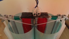
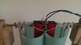
I added only medicinal cotton inside the cilinders but only between the plates and the lateralls wich bonds the paper of each cilinders together (as seen in the pics).
The cottone dampening from insyde must be insyde because the peaks that you see from my measurements (except those from 11khz to18 khz) are even higher and larger with no dampening. So the adennum of the cottone dampening insyde is very good.
Another dampening is the adenum of double adhesive tape directly onto the plates and on top of that a cottone sheet on each plate from a 100% cotton T-shirt for dampening the internall resonances (the red thing applyed onto the plates, as seen in the pics).
Also, two layers of laqueur (50% laq added from where the cilinders meet to outsyde, COMBINED WITH THE "SMALL CUTS" so that will not resonate) smoothens the overall frecv response and enlarges the sweets spot.
This is what i found today. If i think more deeper now i dont want to try to measure the ruban with a cilinder bigger and the other smaller because the smaller one will not emit hights anymore wich is a consequence for making it too rigid..
"
Cheers
Sergiu
SOME MORE HINTS. I will write them down because later i will forget..):
1. The magnets:
*Should they be bigger or smaller in lenght?
Smaller could be costly to achieve the same strenght, but longer could be cheaper if they achieve the same force togheter.
*should they be taller or thinner?
NA (i dont have funds for buying magnets again)
*should they be weaker or stronger?
Stronger it will ad some dB but if the cilinders are not proprely damped and designed those dB's could drive you insane because of the nasty resonances amplified. Also stronger magnets will add dollars in plus to the metal plates (more thicker,or other steel ads more money to the count).
2. Metal plates:
*A very important thing that nobody answered yet: should the plates be 2cm+1cm width so that the flux would be more concentrated or other dimensions like 2+2cm would be also good?
I use the second solution with 2+2cm width because i seen that Wrine's 3cm version bended at 3mm gap. Normally the gap is 4mm, but because i used bigger plates i got 3mm gap without bending.
*what material to use for the plates?
A37 french steel was used in the original design.
AISI 1018 was also used with succes.
Romanian equivallent is OLC15X.
We use colld rolled steel now with succes and i think that with weakened magnets like n42,n38 standard AISI1017, AISI 1018 steel can be used also.
It seems that a larger quantity of carbon diminishez the force and lesser carbon improves force further but saturates more easier. So it must be just as its needed, not too much nore too little quantity of carbon.
3. The gap:
*2,3 or 4mm?
4mm for n48 magnets its perfect, smaller gap could bend the steel..
3mm ads some dB and its the limit of suportability because you can barely keep the coil centered, and as it is the coil could bend from humidity and rub on the plates causing distorsions easily and eventually take the output trannies to their graves as they did to mine .
2mm doesnt add to much stuff, its very hard to center and keep centered the coil. Also if the coil bends only a little bit disaster will strike.
Here we have also a testimony from our colleague tubegeek974:
"PS i use neo magnets from china and 3mm gap on one loudspeaker then tryied 2MM on the other with not mutch more improvements in efficiency but lots of sorrows for centering the bobin!"
4. The coil:
*single sided or double sided?
DOUBLE SIDED FOR SHURE (its the best till now from all the measurements).
SERIES OR PARALEL?
Series its best with +-+- conected and then conected in reverse (best from measurements) .
Altought the series coil measured better than parallel i chose the parallel version in antiphase even for my final setup (when i will finish it) because it gives higher SPL as a consequence of paralelling the coils. 🙂
*Copper or Al?
I found that wirewound copper its very painfull and exhausting and found allot of problems to bonding and keeping it flat..
Flexible copper pcb is a good and very fast sollution, but still too heavy. If it were for me i woul search for a coil made from flexible band that was used in the old walkmans (for the screens and push comands).
For the moment diy hand made Al coils are the winners. They are light, flat, easy to bond and have good contact with the cilinders and now we have flux to solder Al (thanks Wrine).
Wrine used here a laminated AL coil made as found in the cassette players (walkmans) with succes. (Wrine can tell us more about this if he wants)
*overhung or underhung?
Underhung its best (those dB in plus will compensate for conecting the coils in series (if two coils are used in double syded mode).. It measured very good in paralell version too. Instead of 5 turns@ 3cm*50.5cm total exterior dims at the begining of the trials (abit overhung) , now i have 2.6cm*50cm exterior coil dimensions (underhung) and the same is for the interior dimensions.
When going underhund, double sided coil, series or paralell, i sugest making the coil on a former first and then stick the cilinders on it instead of cutting the coils on the cilinders and then sticking them to the former wich has only glue on it.
The overall frecv response of this speaker is very hard influenced on the former quality/or type and material density used for this former. As i tested in my earlier posts you have seen that the double adhesive tape is the worst sollution ever because on the glue on it. A heavy 250gr/sqm foil used for trafos winding between windings, has given so far the best results. I didnt tried lighter foils so far because i couldnt find one.
I also tested 120gr/sqm paper and had very good results but subjectivelly speaking the sound was abit too damped, and when compared to the 250g/sqm foil former, the paper sounded way too daped. The foil sounded more cleaner and seemd to extend better in the very high frecv (sujectivelly speaking).
5. The paper (what kind was tested? impregnated?speacial treated)
I use The Canson paper named "CA" at 120gr/sqm with succes. To prevent the coil from bending you need to add laqueur (allot of it) on the coil to saturate the paper, this will allso soften some dips and peaks.
Wrine: "about the PAPERS i tried. everything under 120 grams can reach 18-20khz. be it with humps and dips. everything above that or the use of excessive glue or epoxy will result in early drop off."
Sergiu: I tried two types of foils (180gr/sqm sandwiched between two coats of paper giving a total of 225gr/sqm and 250gr/sqm pure foil) and the conclusions are: Dont go higer that 180gr/sqm foil (or 225gr if paper damped foil is used)!!!. Its no problem if the 180gr foil has paper sticked on it and gives 225gr BUT if heavier foils than this is used it will dampen the sound too much, making the voice thinner with less dB and the overall frecv resp with higher dips (holes). Both foils reach 24khz (because of the high density) and maybe above that figure BUT because of the high density and mass going higher than 180gr is a no way for shure.
6. The cilinders (dims, diams, shapes)
The optimum dimensions for my 50 cm ruban are 34cm*51cm per sheet (cilinder) to make them round or butterfly and will give you a 4.5cm per half cilinder diameter.
Shapes: well, the round one isnt better, nor best, the shape has to be between butterfly and round because making the cills too round will make them rub on each other and atenuate hights and too butterfly will increase rigidity too much and will dampen unwanted and wanted sounds too much. So its has to bee between them.
Making the coil smaller and cilinders bigger will definetly increase lows but will decrease hights so we have to be carefull here. Wrine is testing this theory right now and could tell us more if he wants.
Wrine tested a version of ruban with a cilinder cuted down, and just one active, but didnt measure good (see the posts behind), so this way is a no go.
I tested two versions, one with a cil shrinked and the other bigger and another version with both cils shrinked and the conclusion from measurements are:
"Now the measurements from one cil smaller (3cm per half) and the other bigger(4cm per half) and then both shrinked at 3 cm per half.
The conclusion as seen in the graphs, is that both cils shrinked gives a smoother overall frecv response BUT doesnt go up to 24KHZ in stead i goes up to 20khz and rolls off smoothely...
When listened to both variants, to my ears the "both cils shrinked" variant sounds restrained wich gives the impression that the membrane has harden too much... The "one cil smaller then the other" vers wins the bet to me Wrine.
I dont see any of these to be used in the future because they dont resolve our problem and the version with one cill bigger and the other smaller its abit harder to make and i can barelly keep the coil into the gap without rubbing."
Some aspects regarding PVC foils:
"Now to see even further how the dims of the cilinders influence the overall frecv i shrinked the cilinders and measured 5 times each at 5 mins distancejust to be shure.
Now you know i told you that i had 34cm@ 51.5 cm hight on the first ruban@4.5cm per half cilinder ; in these measurements i measured in the originall state (dims) and then shrinked at -1cm from each syde making a sheet for one cilinder 32cm@3.5cm per half cil and then -2cm pe syde making the sheet for each cilinder 30cm@3cm per half cil.
Be aware!!! these measurements are valid only for this type of foil and maybe for a foil with paper on one syde; on my paper versions the results where totally reversed.
As you can see the shrinking the cilinders is causing the dips to be deeper so its worsening things up. As i sayed 34cm@51.5or 51cm for the 50cm ruban is optimum.
Subjectivelly speaking on the original version everithing sounds good, then shrinking the cils with -1cm@@3.5cm/half@32cm per sheet, makes the lower voice (bass voice) abit thinner but its no problem since it would not go down there when coupled with a woofer and this seems to be the limit (smallest cilinder diam possible without affecting the overall performance for foil and i suspect the same in the paper versions), BUT when shrinking further at -2cm@3cm/half@30cm, subjectivelly speaking, the overall sound seems restrained, and here i mean lows, mids, and hights.
To me the best was leaving the originall dims as they are at 34@51cm (i trimmed abit the hight for better verticall centering)."
7. The cuts:
* First of all you have to make the cuts on the interior of the coil to lower the overall mass of the coil and for increasing the hights (for me 20pcs of 8 mm diam rounded cuts inside the coil did the magic).
* make the coil smaller with 1 cm and then centrate the coil so that you have exactly 5mm above and 5 mm bellow; this will leave the coil move more freely in the top and bottom, lower the mass and make the sound more fuller, more relaxed (subjectively speaking); this will also separate the rigid portion of the cilinders (where you have the hinges or elastics bolted) from the coil thats why i heard what i sayed "make the sound more fuller, more relaxed (subjectively speaking)".
* The exterior of the cilinders:
- i have tested rectangular and triangular cuts and the winner is definetly the triangular shape cuts;
- the bigger they are the better, BUT if you make them too long or large you will add a sweet spot in the listening area and they will decrease the integrity of the coil and could bend as i experienced on the side where the BIG cuts where made.
Tested and found out this:
The best from all of them is the CLASSIC variant with small cuts, and you cand see in the "VS" graphs why (there you will find the best measures from each).
Tested so far 24cuts (75% and 50% deep), 12cuts(50%and 30% deep), 10cuts (50% and 30% deep) and 10 rectangular cuts (4cm*5mm and 2cm*5mm~5 to10% cutted down from the overall speaker surface) on each cilinder on each syde.
Conclusion: the cuts have to be not higher than the 30% wich means 5.5cm hight in the active area, and no more or less than 2.2cm base lenght (when they are cutted they remain like a equilaterall triangles like in the pic with the membrane bellow) and NO MORE THAN 10 PCS. The base of the triangles has to be equal with the space between the cuts . If you do them higher then the coil tends to bend, if you make them with the base bigger (more than 2.2cm) or make more cuts than 10 not only that will make the coil bend but this will favorise the peaks, dips and distorsions, and i think this is definetly has to do to the fact that you make the space between the cuts smaller, and this space linearise the frecv resp and dampens the peaks.
I found the optimum dims for suspension cuts are 5mm from the laterall of the bonding between the coil and cills and 5 mm from the top of the membrane.
8. Suspensions
Tested yesterday:
"The elastic version has bigger dips than the hinges. The dinamics are the same (subjectivelly)and the sensitivity is a tiny bit more on the elastics but not for going this path because the dips rise higher even where you dont expect. So this aspect is solved for me. "
Elastics are a no go but i will love to use them. Today i will buy some rigid versions of elastics to test even further. But for now hinges are the winners.
If you want to go with the elastics version (because its easyier to change the membranes and recenter the coil in the future) i've tested and the finall conclusion is:
The softer the elastic is, the higher you go with the peaks and even higher with distorsion. The more tensionned you add to it, the dist goes down to almost half..
Another important aspect is that when tensionning the elastics more, the sounds comming from insyde the cuts vs between the cuts are almost the same (in a good way), except at the hights where each "covers" the other abit (the sounds from insyde and between the cuts).
Another aspect is that the ropes are a NO GO because they dont keep the coil in place at high peaks and large movements.
Thinner elastics vs thicker ones: the thinner the elastic the weaker the strenght=the higher the distortions. I now use a big elastic composed from 8 small elastics wich was the best for me..
9. Glue used
The best combo for me was first add laqueur to all the coil with the cilinder and all the other cilinder in layers till saturating the paper, then add dots of super glue on the coil like a square on the edges of the coil and dots of super glue between the round cuts inside the coil; bond the cilinders toghether fast and put a big heavy box on it and let it dry for two hours, and then 5 mins of hair drier hot air blown on it and let it cool 30min to 1hour in an opened space. (this is the method that i used)
I used double adhesive tape with laq onto the cils to bond directly the two sided coils and the cilinders toghether; the bonding was made directly onto the coil area with succes and good measurements.
Even better results where obtained when the former for the coil was 4.4cm @51cm hight and the sheets for the membranes where 34 or 32cm by 51 cm hight. Then sticking the cils right on the 4cm area and leaving 2 mm on each syde to move freely outsyde of the rigid area of the center (same results for foils and paper membranes).
10. Dampening
I added only medicinal cotton inside the cilinders but only between the plates and the lateralls wich bonds the paper of each cilinders together (as seen in the pics).
The cottone dampening from insyde must be insyde because the peaks that you see from my measurements (except those from 11khz to18 khz) are even higher and larger with no dampening. So the adennum of the cottone dampening insyde is very good.
Another dampening is the adenum of double adhesive tape directly onto the plates and on top of that a cottone sheet on each plate from a 100% cotton T-shirt for dampening the internall resonances (the red thing applyed onto the plates, as seen in the pics).
Also, two layers of laqueur (50% laq added from where the cilinders meet to outsyde, COMBINED WITH THE "SMALL CUTS" so that will not resonate) smoothens the overall frecv response and enlarges the sweets spot.
This is what i found today. If i think more deeper now i dont want to try to measure the ruban with a cilinder bigger and the other smaller because the smaller one will not emit hights anymore wich is a consequence for making it too rigid..
"
Cheers
Sergiu
Hi Sergiu and Wrine , i keep on reading your posts and thank you for sharing your experiences.
i just come to read the whole linaeum Patent and specially the paragraphs about the cutings in the wings and the coil thanks for speaking of that Sergiu .
So i cut 15X 8mm holes in the center of the coil and 25X6mm holes on each wing close to the coil ( 30%) I don't have any measurements but subjectively the lack of highs has disappeared and there is no more need for an extra supertweeter i would even say that it seems to be more efficient !
I will work about how to measure all this soon .
each wing is CANSON PAPER 160g/m2 47X16 CM
the coil is Double side coper printed board 10turnsX2 = 9 ohms serial /weight 17g
total weight of the 4wings +coil = 60 g
i use elastic suspension with some bracelet wire i don't know what material it is white, thin and strong ... ( silicon? )
Hi Michel,
After seeing you realisation from the post above wich is situated here http://www.diyaudio.com/forums/plan...on-speaker-different-kind-80.html#post4746885 i also wanted to test different types of elastic tensioning, so i did. Bellow you can see what i measured.
I wanted to tension 4 elastics as you did Michel in you version but i tought its woo much of a headache so i improvised to be something like yours (named it "short elastics").
The results are not so bad as you can see in my measurements, only the dip i pointed out at 6khz region with the pointer has lowered with aprox 2dB and the hights in your version goes down with 3dB after 20khz to 23khz (mine goes up with 3dB in that region) so its not bad. In your version two 30cm long elastics was used with succes to tension the membrane and left an aprox 3 cm elastic in plus after the node (as seen in the pics).
My version uses two 40cm elastics to proprely apply tension to the membrane (and a 3 cm surplus remains after the node as seen in the pics). The actual problem is the subjective listening tests. It seems that your version of tensioning cuts in half the spatiality, the finesse of the hights and the roundness of the voice. Strange thing. To me its seems that you have to be very carefully with the tensionning in this case, and what i encountered seems to be a consequence of the coil being too restrained, or this type of elastics hardens very hard the active portion and doesnt resonate too much at hights and mids...
I didnt have the time to revert back to the longer elastics today but will go back to that version tomorrow because with this short elastic tensionning method my 4th ruban now sounds flatter than the paper former wich sounded worse earlyer.
The only advantage that i see to your version is that when going full range, the coil remains elegantly centered in the gap no matter what bass or how hard you stress it BUT this speaker, as it is, its not suposed to go full range. It should be cut at 200-250Hz so, i personally prefer this longer elastic version.
Cheers
Sergiu
Attachments

Last edited:
Well i found the problem on IV version: it seems that the front is bonded corectly and the back , well, the back is NOT.
The conclusion is that PEOPLE BE CAREFULL AT GLUING THE FORMER TO THE CILINDERS. If its not bonded proprely you have peaks and resonances. You can easily check this with a mic, and if the back measurement differs too much from the front then you have a bonding issue.
To continue with my measurements i will use the front wich has lower resonances and has lower peaks and dips.
Look at the pic that i draw bellow and you will see what i meant. As you can see in the back, the glue has drained down leaving too much of the former exposed, but in the front, because i have seen the laq and the super glue from the back draining down i applyied the gue when the ruban was laying horizontally (its the best way to rectify the membrane if it doesnt bond from the start).. I draw it because you couldnt see it in the pic..
nice finding dude !! already thought it had to be something mechanical good job finding out what it was! ! cool drawing btw 🙂 haha
Thanks Sergiu,
very nice experimentation , I confess i haven't payed mutch attention about the length of elastics and how they are set . The first versions of Deminieres (fd acoustic) where hanged like mine but your remarks are very clever and probably it has some influence on the sound , i will try long elastics and telle you about this .
I'm actually thinking of trying another type of wings with 2 diferent materials sticked together on a vertical line : one for the inner part that radiates and the other for the exterior part that is essentially a hinge . According to your experimentations the inner part must be the lighter and the ext the harder... what you think?
regards
Michel
Hi Michel,
I didnt quite understand the part from here:
"one for the inner part that radiates and the other for the exterior part that is essentially a hinge . According to your experimentations the inner part must be the lighter and the ext the harder"...
I did experiment with one cilinder smaller and the other bigger with very good results, BUT i havent choosen it because of the poor dispersion... I have used same paper for both cilinders. The fact is that the bigger cilinder has a good dispersion and the "hinge" cilinder doesnt have it. The smaller cilinder radiates a restrained sound as a consequence of the fact that its smaller, wich makes it more rigid, and maibe has fewer dB. The bigger cilinder doesnt have this problem so it radiates happpyli a smooth sound. Because of this behaviour, when you position the speaker in your room the bigger cilinder of the speaker should be facing you and the smaller one pointing at the exterior.
In this ruban you wont perceive a 180 degree like, radius dispersion , instead you will perceive something like 90degree wich i dont like or want.
Another aspect is the centering. When using paper for the cilinders, the smaller cilinder acts like a spring, pulling the other cilinder and making it rub on the metal plates. Even with hard tensioning with elastics i had the same probl especially at hight volumes when higher vibrations are produces.
This is what i experienced with this version.
Cheers
Sergiu
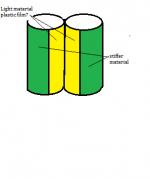
not stick something onto the foil : but make a wing with 2 different compositions a very light material in the middle and a stiff one on the edges and the the light one sticked to the stiff one following a vertical line like on the pic .
in my opinion the middle needs to be the stiffest. since otherwise it will form a hinge and wont transfer much to the rest.
Ok Wrine , we just have to try different combinations of materials and relative sizes of each ;Then listen and measure and we'll know what is best.
i'm actually working on some electret mic and preamp to get good measurments
i'm actually working on some electret mic and preamp to get good measurments
the Panasonic capsule is only 3 dollar but the problem is how do you calibrate it ? i really think the umik was the best investment i did in years. calibrated and all so no more screwing around.
and tubegeek i always try and measure 🙂 dont worry, i for once still have the peak problem in every design ever used so far. a dip and a peak. 🙁 we can reach high but the randomness in the high end is bugging me 🙁 still thinking of a solution of some sort. what if we would use one heavy cylinder and one light one ? the heavy one being so heavy or dampening it wont reach to the problem ferquency
and tubegeek i always try and measure 🙂 dont worry, i for once still have the peak problem in every design ever used so far. a dip and a peak. 🙁 we can reach high but the randomness in the high end is bugging me 🙁 still thinking of a solution of some sort. what if we would use one heavy cylinder and one light one ? the heavy one being so heavy or dampening it wont reach to the problem ferquency
Hi Michel,
I did my onwn preamp, but buyed a electret mic. Are you shure you want to do this? And how?
I also found an interesting article written by l'audiophille staff here micro.
😉
Very interesting article.
Cheers
Sergiu
to bad it is in french 🙁
Wrine :"the Panasonic capsule is only 3 dollar but the problem is how do you calibrate it ? i really think the umik was the best investment i did in years. calibrated and all so no more screwing around."
Thank you Wrine , i think someting like te UMIK is exactly what i need to go further in my investigations .
Sergiu: "also found an interesting article written by l'audiophille staff here micro.Very interesting article.Cheers
"too bad its in french" said Wrine..
I own the whole collection of "the Audiophile " and red this article again : very interesting indeed but its more for recording than measurement, so not what i'm looking for at the moment. If there are some paragraphs that both of you want me to translate in my approximative English, i can try to do this for you .
regards Michel
michel
Hi Michel,
Thanks. I also understand french, i made my Hiraga modified 30w amp from the original article wich doesnt have translation.. 😉 i'm very bad at speaking or writing but i understand it pretty well.
I have to do some more measurements tomorrow for the cuts and then will chose a final version for myself. Cant wait.🙂
Cheers
Sergiu
QUOTE=WrineX;4757439]the Panasonic capsule is only 3 dollar but the problem is how do you calibrate it ? i really think the umik was the best investment i did in years. calibrated and all so no more screwing around.
and tubegeek i always try and measure 🙂 dont worry, i for once still have the peak problem in every design ever used so far. a dip and a peak. 🙁 we can reach high but the randomness in the high end is bugging me 🙁 still thinking of a solution of some sort. what if we would use one heavy cylinder and one light one ? the heavy one being so heavy or dampening it wont reach to the problem ferquency[/QUOTE]
You are right. Now i regret that i didnt buyed a umik. With separate blocks (phantom psu, preamp) i had some headacke..
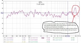
I too have the peak and the dip problem. Altought they did flatten abit, they are still there. But i really suspect that the dip its there because of the uncomplete bonding process. The peak is there because both cilinders have it at a lower amplitude, as seen in the off axis frecv response, and because they both have it and emitting it at the same time, their amplitude almost doubles in measurements, altought subjectivelly we dont perceive it. I suspect that this phenomena is perceived by the mic like in the situation where you dont make the cutting point correctly for a speaker filter, and both speakers are cutted lower (for the hights) and upper ( for the bass) and they reproduce the same frecv in that point. Exactly as you told me Wrine on skype.
That is what i think and deduced from the measurements made till now.
Cheers
Sergiu
and tubegeek i always try and measure 🙂 dont worry, i for once still have the peak problem in every design ever used so far. a dip and a peak. 🙁 we can reach high but the randomness in the high end is bugging me 🙁 still thinking of a solution of some sort. what if we would use one heavy cylinder and one light one ? the heavy one being so heavy or dampening it wont reach to the problem ferquency[/QUOTE]
You are right. Now i regret that i didnt buyed a umik. With separate blocks (phantom psu, preamp) i had some headacke..
I too have the peak and the dip problem. Altought they did flatten abit, they are still there. But i really suspect that the dip its there because of the uncomplete bonding process. The peak is there because both cilinders have it at a lower amplitude, as seen in the off axis frecv response, and because they both have it and emitting it at the same time, their amplitude almost doubles in measurements, altought subjectivelly we dont perceive it. I suspect that this phenomena is perceived by the mic like in the situation where you dont make the cutting point correctly for a speaker filter, and both speakers are cutted lower (for the hights) and upper ( for the bass) and they reproduce the same frecv in that point. Exactly as you told me Wrine on skype.
That is what i think and deduced from the measurements made till now.
Cheers
Sergiu
QUOTE=WrineX;4757439]the Panasonic capsule is only 3 dollar but the problem is how do you calibrate it ? i really think the umik was the best investment i did in years. calibrated and all so no more screwing around.
and tubegeek i always try and measure 🙂 dont worry, i for once still have the peak problem in every design ever used so far. a dip and a peak. 🙁 we can reach high but the randomness in the high end is bugging me 🙁 still thinking of a solution of some sort. what if we would use one heavy cylinder and one light one ? the heavy one being so heavy or dampening it wont reach to the problem ferquency
You are right. Now i regret that i didnt buyed a umik. With separate blocks (phantom psu, preamp) i had some headacke..
I too have the peak and the dip problem. Altought they did flatten abit, they are still there. But i really suspect that the dip its there because of the uncomplete bonding process. The peak is there because both cilinders have it at a lower amplitude, as seen in the off axis frecv response, and because they both have it and emitting it at the same time, their amplitude almost doubles in measurements, altought subjectivelly we dont perceive it. I suspect that this phenomena is perceived by the mic like in the situation where you dont make the cutting point correctly for a speaker filter, and both speakers are cutted lower (for the hights) and upper ( for the bass) and they reproduce the same frecv in that point. Exactly as you told me Wrine on skype.
That is what i think and deduced from the measurements made till now.
Cheers
Sergiu[/QUOTE]
well you do perceive them, be it that we are not that well made to hear differences that high. we tend to hear changes a bit lower with more ease.
for me if the mic says its there(in a proper measurement) its there. having problems with it is a another thing 🙂 hehe
Cheers
Sergiu
well you do perceive them, be it that we are not that well made to hear differences that high. we tend to hear changes a bit lower with more ease.
for me if the mic says its there(in a proper measurement) its there. having problems with it is a another thing 🙂 hehe[/QUOTE]
Here are my extended research from today. I measured only the 3rd version because i ruined the 4th ruban when trying to bond it correctly 😀 .
I have written all my comments in the pics.
Cheers
Sergiu
Attachments
-
 3 off axis.jpg135.3 KB · Views: 342
 -
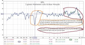 3 green =between cuts & blue =insyde.jpg155.9 KB · Views: 346
 -
 3 pink is off axis and red is on axis.jpg197.6 KB · Views: 346
 -
 3@ on axis@no cuts =red@blue=with cuts.jpg188.1 KB · Views: 340
 -
 3@blue is on axis=front of speaker@green is off axis insyde one cil with mic oriented to the coi.jpg141.9 KB · Views: 325
 -
 3@off axis@between cuts is dark red@on axis is green.jpg125.1 KB · Views: 137
 -
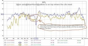 3@on axis@blue=front@yellow is on top where the cils meet.jpg143.6 KB · Views: 151
 -
 Yellow is on axis ON TOP@green is off axis insyde a cil with mic oriented to the coil.jpg126.6 KB · Views: 163
- Home
- Loudspeakers
- Planars & Exotics
- A DIY Ribbon Speaker of a different Kind