😀 If you can realize this, I'll be the first buyer of the updated version of the module.good idea!
😀 If you can realize this, I'll be the first buyer of the updated version of the module.
Thanks, our multichannel products always sync all the clock.1-2 channel products have not now.
Yeah, let the customers do your R&D. 😉
Thanks, good idea good products, better suggestions better improvement.
If you are unhappy with the f3 of the amplifier module then replace the coupling caps with something larger.
Synchronising the PSU to the amplifier chip would only work if the frequency of operation of the two match. This is highly unlikely as the amplifier switches far faster than most SMPSs do. Not only this but if the SMPS uses a resonant topology then the switching frequency will vary with load making synchronising the two impossible. Don't worry though none of this is a problem.
Doc is absolutely correct though, the energy storage before the transformer is what you want to beef up if you're interested in improving the peak/transient capabilities of the PSU. This is the most important for frequencies below the line frequency but really you need to measure before you go shooting in the dark.
The most obvious thing is that the amplifier has rolled off bass due to the coupling caps, but then so do all amplifiers. Either calculate the f3 from the square wave or measure/calculate it from known circuit capacitances and impedances. Once you've found the problem (if it even exists) you can attempt to fix it.
If you are unhappy with the f3 of the amplifier module then replace the coupling caps with something larger.
Synchronising the PSU to the amplifier chip would only work if the frequency of operation of the two match. This is highly unlikely as the amplifier switches far faster than most SMPSs do. Not only this but if the SMPS uses a resonant topology then the switching frequency will vary with load making synchronising the two impossible. Don't worry though none of this is a problem.
Doc is absolutely correct though, the energy storage before the transformer is what you want to beef up if you're interested in improving the peak/transient capabilities of the PSU. This is the most important for frequencies below the line frequency but really you need to measure before you go shooting in the dark.
The most obvious thing is that the amplifier has rolled off bass due to the coupling caps, but then so do all amplifiers. Either calculate the f3 from the square wave or measure/calculate it from known circuit capacitances and impedances. Once you've found the problem (if it even exists) you can attempt to fix it.
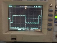
Thank you for your suggestions, all the 4 units coupling cap value are 10uf/50v/X7R, c36/c37/c39/c40, chang it's value to 100u/16V/X7R , test photo below.
Attachments
Last edited:
Thank you for your suggestions, all the 4 units coupling cap value are 10uf/50v/X7R, c36/c37/c39/c40, chang it to 100u/16V/X7R , test photo below.
Great! 😀
So what are the red WIMAs if not coupling caps?
Well, you checked for the influence of DC-Bias - do they have similar potentials on both side? 100uF 16V will suffer from this effect alot if in the same footprint as 10uF 50V.
100u/16V/X7R
Well, you checked for the influence of DC-Bias - do they have similar potentials on both side? 100uF 16V will suffer from this effect alot if in the same footprint as 10uF 50V.
Last edited:
WIMA in the output filters.So what are the red WIMAs if not coupling caps?
Сoupling caps unfortunately ceramic.
There is a voltage not exceeding 5V.Well, you checked for the influence of DC-Bias - do they have similar potentials on both side? 100uF 16V will suffer from this effect alot if in the same footprint as 10uF 50V.
Measured. DC offset of 3.79V.
Unfortunately the exact schematic diagram of the module is not present.
Doc, may be better to replace the electrolytic capacitors?
Last edited:
Electrolytics are fine, even if i'm not a fan of these as coupling caps. Regarding the MLCC ceramics, 3.8V gives you the static DC-Bias and corresponding capacitance loss. Additionally you'll have capacitance modulation by your applied AC-Signal. Effects rise at low frequency - i wouldnt call this an issue for frequencies above i.e. 250Hz, but IMD might rise to. Question is, will you hear it? 🙂
Looking at this, you'll see that having 50V X7R ceramics suffer less from this effects than having 16V X7R ceramics in the same place.
So leave the lytics.
Looking at this, you'll see that having 50V X7R ceramics suffer less from this effects than having 16V X7R ceramics in the same place.
So leave the lytics.
Measuring 50 Hz square wave indirectly shows the lower frequency limit. If the square wave is flat, then the amplifier may sound ideally from 0 hz. If the square wave is not flat, then the problem is with the power supply or there is insufficient capacity or the coupling capacitor.
I have subjective a lack feelings of low frequencies.
Certainly a 50Hz square shows low frequency rolloff. But the slope measured indicates a corner frequency definitely below 10Hz, maybe 3..5Hz. Ridicolously low anyway, nothing relevant to audible bass response. Who told you that a perfect square of 50Hz is relevant to audio quality?
Oh! If the music signal consists solely of the sinusoidal signal!Who told you that a perfect square of 50Hz is relevant to audio quality?
I'm not saying that it is the truth. I have only subjective opinion. Amplifier V200, with a flat meander produces and good bass. In TPA3251 bass is not enough. I do not know how to solve the problem. Therefore, I am looking for different ways. Power supply, continuous capacitors, high output impedance of the bad inductors....
Probably need a set of measures for good efficiency at low frequencies.
In fairness, I want to say that this module produces a very beautiful sound. And a very good stereo localization. Compared to Pass Aleph and I.AM.D V200.
Last edited:
No name core diameter of 21mm. Copper wire diameter of 1mm.What's about the inductors?
Ordered Coilcraft VER2923-103KL. Waiting...
Last edited:
Are they getting hot at idle? What's their measured impedance and what's wrong with 1mm wire diameter? The inductors on the EVM are 1mm as well on a 106-2 core. So, without knowing the cores material how you judge they're bad/undersized?
So you're unsatisfied with a lot of parts and performance?
They state that the board does 2x140W into 4R at 1% with this parts. That's what you bought, don't you trust them? 🙂
So you're unsatisfied with a lot of parts and performance?
They state that the board does 2x140W into 4R at 1% with this parts. That's what you bought, don't you trust them? 🙂
I'm on holiday now, therefore no further investigations. What I found out last Saturday was, that the inductors stay relatively cool. I tried to achieve 2x140W at 4Ohm (1kHz sine), but unfortunately the amp switched off at around 2x100W (almost immediately). After a while I tried 2x80W and after approx. 1 minute it switched off again. The temperature at the transformer achieved after this short time approx. 106˚C, measured with an IR thermometer. 2x50W was possible for longer time, I did not test whether it switches off after more than 10 minutes. Also the heat sink was not really hot.
Maybe it's my bad English. I just listed the possible problems.how you judge they're bad/undersized?
no, coldAre they getting hot at idle?
No!🙂 I believe that there is a small disadvantage of bass. But it is not fatal. The overall impression is good.So you're unsatisfied with a lot of parts and performance?
- Home
- Amplifiers
- Class D
- TPA3251d2