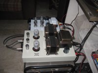
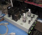
I'm making use of what I have on hand, my power transformer and choke have been taken from another project. The power transformer dictates that I use a bridge rectifier with choke input filer in order to end up with something around 300V. The choke is only 2H and more would be better as it requires a decent current through the choke to have good regulation - around 150mA should do it which fortunately works out for a stereo amp.
I have a small cap between rectifier and choke whose value can be adjusted to fine tune the B+ voltage if necessary. I expect with the 1uF cap I have there right now that I'll end up with around 320V, less if I add an RC filter after the choke. So we have some room to negotiate the B+
if you are using SS bridge, i see no reason to use small cap as first cap, i would stick a 470ufd/450 volt cap in there...
higher voltage is not an issue, it is easy to lose voltage when you need to...
can you tell the unloaded ac voltage of your secondary traffo, the dc resistances of the secondary so we can estimate raw B+
for that matter the dc resistance of your OPT primary, and your desired operating points for your 6AV5?
i have used the 6AV5 and they are indeed good sounding, the 7403 is even better though unfortunately one of them
gassed out and having no replacements i finally ended up with this, 5894.....
Attachments
I'm making use of what I have on hand, my power transformer and choke have been taken from another project. The power transformer dictates that I use a bridge rectifier with choke input filer in order to end up with something around 300V. The choke is only 2H and more would be better as it requires a decent current through the choke to have good regulation - around 150mA should do it which fortunately works out for a stereo amp.
I have a small cap between rectifier and choke whose value can be adjusted to fine tune the B+ voltage if necessary. I expect with the 1uF cap I have there right now that I'll end up with around 320V, less if I add an RC filter after the choke. So we have some room to negotiate the B+
Hi Bigun
Hope after all the work you've done, your choke doesn't buzz or rattle. Then you can use it for choke input. Then it will become an excellent potential energy store, and not just a filter. 😉
Ian
Last edited:
Hey guys, here is what I got for DC quiescent points.
My filament transformer wasn't intended for 1.2A so I needed a little serial resistance to get me ~6.3v, .6R worked good 🙂
Va=262
Cathode resistor is a measured 710R
G1 grounded via 22k
G2 tied to plate via 100R
Tube #1
"Raytheon" It says Raytheon but the silkscreen and little dots make me think it's a GE.
Va-k= 222.4 Vk=39.6 Ik=55mA
Tube #2
Raytheon
Va-k=221.6 Vk=40.4 Ik=56mA
Tube #3
Sylvania
Va-k=220.6 Vk=41.4 Ik=58mA
Tube #4
RCA
Va-k=223.2 Vk=38.8 Ik=54mA
Tube #5
RCA
Va-k=226.2 Vk=35.8 Ik=50mA
Tube #6
RCA
Va-k=220.5 Vk=41.5 Ik=58mA
Tube #7
RCA
Va-k=221.5 Vk=40.5 Ik=57mA
The one RCA tube that tested 50mA had different internal electrode connections at the bottom than the other three. Other than that the plates look identical, big holes on two sides. I can take some pictures of my specimens. Looking at the RCA RC-12 average plate characteristic graph for the 2A3 it would appear the 6AV5GA would bias up very similar in a like for like circuit; Va=225 Vg-k=-40 Ia=50mA
if you are using SS bridge, i see no reason to use small cap as first cap, i would stick a 470ufd/450 volt cap in there...
higher voltage is not an issue, it is easy to lose voltage when you need to...
I couldn't agree more but I think Bigun is reflecting Ron's build which has a pseudo choke input via a small reservoir cap. Unfortunately I think a larger choke is in order, something more like 10H. To get ripple down with the 2H you will want a bigger C after the choke, which would in turn probably make the choke vibrate more. Maybe not. Hopefully all of Bigun's efforts yielded a much quieter choke.
Since you want your Va ~250V, and your cathode resistor is already determined to be 720 ohms you must have a good idea of how the load line will look you will probably find the 6AV5 will draw a little over 50mA and the Vk will settle in at 37V - Vak will probably be 215V+37V = 252V - Also kind of "classic" values for 2a3
Hi Ian, very close indeed. That graph you provided from Mr. Parks seems accurate and a good resource for anyone planning on using the 6AV5GA.
I couldn't agree more but I think Bigun is reflecting Ron's build which has a pseudo choke input via a small reservoir cap. Unfortunately I think a larger choke is in order, something more like 10H. To get ripple down with the 2H you will want a bigger C after the choke, which would in turn probably make the choke vibrate more. Maybe not. Hopefully all of Bigun's efforts yielded a much quieter choke.
i doubt that the gapping in that choke was really meant for 300mA, it can also be the cause of buzzing, using a cap input psu is better....
btw, looking at your tube testings, i did not see any significant difference, you can use them and not hear any difference in sound....
i doubt that the gapping in that choke was really meant for 300mA, it can also be the cause of buzzing, using a cap input psu is better....
No I think it's a 200mA choke? He has at least 300mA, the DC current he tested was ~145mA (318/2k2) and then there was the ~180mA of ripple current through the 50uF cap.
btw, looking at your tube testings, i did not see any significant difference, you can use them and not hear any difference in sound....
I doubt I would hear a difference too. I will most likely use tube #6 and #7, they seem like a good match. I didn't test gm though.
Member
Joined 2009
Paid Member
post #324: I amif you are using SS bridge
post #324: it was 520Vcan you tell the unloaded ac voltage of your secondary traffo
post #376: I will treat the 6AV5 as if it were a 2A3your desired operating points for your 6AV5?
me too!!Hope after all the work you've done, your choke doesn't buzz or rattle.
I agreeThen you can use it for choke input.
I'm relying on Edcor spec, it's an XC87-2H-300i doubt that the gapping in that choke was really meant for 300mA
if needed, I have a pair of Hammond 158M 10H 100mA chokes I can steal from another project but prefer to leave that one intact for a bit longer if I canI think a larger choke is in order, something more like 10H
Morgan Jones' Valve Amplifiers has a discussion about choosing values for a choke input filter, and how to tell if your choke meets the current requirements. When I did a test case following his figuring, it came out that a choke input filter will always require that the choke have a much higher current rating than what the circuit will be drawing.
For 6AV5GA, the ones with no big square holes in their plates are good for up to 20W plate+screen dissipation, according to Mr. Tubelab. That would bring the tube's internal plate resistance down, which would give you better damping to the speaker, and I'd expect lower distortion too. I'd aim for between 18 and 20 watts plate+screen dissipation per 6AV5, so maybe something like 250V plate-cathode, and about 75mA plate+screen current draw, for 18.75W plate+screen dissipation. That way the amp might come out sounding better than with a 2A3 in it. (Maybe...)
I just put a pair of 7H 120mA Thordarson chokes and 800uF 330V electrolytics (CLC) into my PP 2A3 amp. No hum at all, even with AC filaments. I'd been listening to a TPA3116 amp, just to see if I could live with it as my 'hot weather' amp. I'm not sure I can. The PP 2A3 sounds so much smoother in the highs. No gristle through the tubes, but plenty of high frequency sizzle from the class D amp. I think I'm just a tube guy, no way around it. Some people are, I guess.
--
Member
Joined 2009
Paid Member
I have been offered a Hammond 193H if I need it, 5H but a beast to carry around. Let's see how the 2H works out after the varnish is dry. There'll be something interesting to learn from this one way or the other so nothing is a waste.
By the way, there's a lot of options between a tube amp and a cheapo Class D if you want lower heat. Try a good quality Class AB SS amplifier.
By the way, there's a lot of options between a tube amp and a cheapo Class D if you want lower heat. Try a good quality Class AB SS amplifier.
post #324: it was 520V
250v at 60mA is a 4.2k load, what is the OPT primary dc resistance?
if you are using 750 ohms cathode resistors,
then you add all of them up to come up with total load.
and two times that loads up your power supply...
what are the dc resistances of your power traffos?
we can estimate the thevenin equivalent circuit by knowing
unloaded ac terminal voltage of your power traffo
and the secondary dc resistance referred to primary...
Other than that the plates look identical, big holes on two sides.
George found that the ones with the holes in the sides couldn't handle so many watts. So your operating point might be the best you can do with that load.
Ian
Member
Joined 2009
Paid Member
The purpose is to try out some driver options and share the experience with Ron in case it's helpful for him. My power supply and OPT are different from his - I'm on the cheap side based on my parts bin, he's on the fancy side based on what he said earlier. Therefore, I don't think I can replicate his system exactly so we don't need to go overboard on the analysis.
My OPT gives the option of a 5K : 8R winding and this seems like the best starting point (Ron has a different option). The load is not going to be a resistor, it will be a speaker with a varying impedance so we can only calculate an 'ideal case' easily.
I'm not aiming for pushing the power dissipation Tubelab-style but rather finding something close enough to allow me to play with some driver tubes. For the final build I will revisit both the power supply (adding snubbers, 'better' diodes) and operating point for the power tube.
My OPT has a DCR spec of around 65 Ohm if I remember correctly although I measure closer to 100R. The power trafo has a secondary DCR that I measure at 50R and the Choke has a DCR of 20R or so, meaning it's a low impedance power supply at DC compared with most (something I had in mind when I bought this iron).
I don't have a 750R cathode resistor on-hand so I'll probably end up with a slightly different value. I have some chunky 680R resistors I could use if running the tubes a bit hot, I also have some 2k2 power resistors and 3 of them in parallel would give me 733R which sounds pretty useful.
FWIW, in my 5894 set amp build, the output stage runs from a lower B+ than the drivers, a 12at7 aikido style voltage gain stage feeding a 6cg7 cathode follower running off a B+ of 420 volts dc....the output tube runs 30 watts plate dissipation......
all i am saying is that knowing the dc resistances in your psu and loads, you can predict the extent of voltages with load, and predict what the loaded B+ will be.....
all i am saying is that knowing the dc resistances in your psu and loads, you can predict the extent of voltages with load, and predict what the loaded B+ will be.....
Member
Joined 2009
Paid Member
I am thinking about a voltage doubler option for higher B+ for the driver stage - I see you are using a totem pole so the higher voltage makes perfect sense. I was thinking of higher B+ so that I could use a larger resistive load for a simple high Ri triode like 12AX7. This would allow the 12AX7 to operate more like the classic L-W design where people have reported very good results using the 12AX7. Some people have not been so happy with this driver. Apart for ability to flow current I think one reason for that is because you need a high load impedance to get the good linearity that the 12AX7 is capable of (Merlin liked the 12AX7 linearity a lot!). I also will try a triode-wired pentode driver stage.
i forgot to mention, since i make my own traffos, the driver stage is powered by a separate winding in the power traffo....
my experience tell me two things, higher B+ for input steage works fine and getting them from a separate supply is even better in terms of clarity...
i can only empathize with you being limited in your choices by what is available in the market in terms of power traffos...
i am not limited in that respect since i can make them to my needs...
one last question, what is the part number of your power traffo so i can look more closely...and form a clearer picture....
Neat 🙂
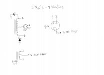
Good power supply option for sweep tube pentode operation, Tall filter 250v for plate and short filter 125v for the screen.
Good power supply option for sweep tube pentode operation, Tall filter 250v for plate and short filter 125v for the screen.
since i am fond of sweep tubes, i use voltage doublers,
the center voltage is good for the screen supplies......
power traffo design and build then becomes extra simple as
no high voltage windings are present and so no creepage to worry about....
imho, it is high time for edcor and hammond to come out with
modern day offerings in their tube power traffo line-ups...
Patrick Turner has a very good webpage about tube power supplies...powersupplies
- Status
- Not open for further replies.
- Home
- Amplifiers
- Tubes / Valves
- 2A3 driver