I would be interested in a few of these boards... 😀
if order a few I'll let you know guys I really don't want to have spare ones collecting dust in my room 😛
but yes, in the "sales section of diy not here"
Regards
Juan
if order a few I'll let you know guys I really don't want to have spare ones collecting dust in my room 😛
but yes, in the "sales section of diy not here"
Regards
Juan
Please send me a PM if/when boards become available.
Thanks!
Please send me a PM if/when boards become available.
Thanks!
no problem man, I'll let you know 🙂
Best Regards
Juan
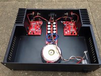
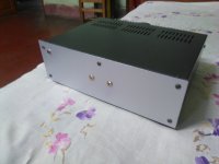
My 100Watts IRFP250N MOSFET power amplifier.
Attachments
-
 6286_402745689917858_6582271711393715595_n.jpg106.8 KB · Views: 1,033
 -
 10325562_402745743251186_3188944325685266981_n.jpg103.6 KB · Views: 1,020
 -
 10445504_402745673251193_7249906208267794066_n.jpg151.6 KB · Views: 984
 -
 10986564_402745786584515_6681899173457801770_n.jpg93.4 KB · Views: 949
 -
 11226911_402745659917861_3212077535782893745_n.jpg104.5 KB · Views: 891
My 100Watts IRFP250N MOSFET power amplifier.
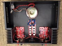
Looks nice and clean, however ... did you try to run it at 70-100W output power during a long time - more than 30 minutes? Based on my experience, heatsinks of this size are going to run really hot.
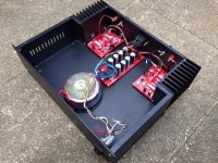
Very nice work reji.
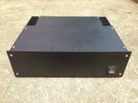
Did you make the case yourself?
Thank you. Case is done with the help of sheet metal working shop in my home town, i took the drawing with all the measurements and heat shink . they also did the matt powder coating.
Now im using only 35VDC rail and 50ma quiscent current with gale bookshelf speakers , its really not getting too hot in long run . i want to change the transformer with 45VDC rail in 4ohms load.Looks nice and clean, however ... did you try to run it at 70-100W output power during a long time - more than 30 minutes? Based on my experience, heatsinks of this size are going to run really hot.
Now im using only 35VDC rail and 50ma quiscent current with gale bookshelf speakers , its really not getting too hot in long run . i want to change the transformer with 45VDC rail in 4ohms load.
You have plenty of room, do try making two separate PSU boards ea with own rectifier bridge and caps. The improvement in sound stage is quite dramatic.
Diodes and caps are cheap relatively and this is a major upgrade in SQ for the effort expended.
Very nice box!
You have plenty of room, do try making two separate PSU boards ea with own rectifier bridge and caps. The improvement in sound stage is quite dramatic.
Diodes and caps are cheap relatively and this is a major upgrade in SQ for the effort expended.
Very nice box!
Actually i designed the case for dual mono, but i ended up with stereo. Thank you for advice.
I generally run a test on the bench to see what resistive load the amplifier can drive without the output voltage collapsing. This requires good heatsinking to prevent overheating of output devices and I restrict the duration of the test so that temperature de-rated SOAR is not exceeded.Looks nice and clean, however ... did you try to run it at 70-100W output power during a long time - more than 30 minutes? Based on my experience, heatsinks of this size are going to run really hot.
Typical unclipped sinewaves for a 100W amplifier would be:
29Vac into 8r0 for minutes. (105W from a ±50Vdc PSU)
27Vac into 4r0 for ten seconds and allow to cool for >30seconds. (182W)
24.5Vac into 2r67 for two seconds. (225W) and allow to cool for >30s
But recently I saw a post criticiisng chinese heatsink aluminium and they showed the identical chassis that I already had.
Thinking: this deserves a more thorough test !
I set the amplifier to output ~ 35% of maximum power (17Vac) into a big (450W) 8r0 load.
And monitored the heatsink and the output device temperatures.
chinese aluminium is good enough. The maximum temperature I recorded during this 60minutes continuous torture test was Tc<70°C in an ambient of 21°C Ts <65°C giving a delta Ts-a of ~44Cdegrees.
I would expect the Delta Ts-a during very loud domestic listening to be much less than 20Cdegrees. My amp will not overheat.
PA03 Mission Complete
Finally, I received the last bits and completed the PA03; a PCB designed by Pavel Dudek and made by Sjöstrom audio! Yes, of course I had to add two VU-meters. It is kinda my thing I guess 😉.
Hereby some pictures, I hope you all like it:
.JPG)
.JPG)
.JPG)
.JPG)
.JPG)
.JPG)
.JPG)
I made a little YouTube video in which you can see the VU's and the fade-in effect of the LED's that emit the VU's when the amplifier is just powered on: Link. Also you can find more pictures at my Flickr gallery.
Finally, I received the last bits and completed the PA03; a PCB designed by Pavel Dudek and made by Sjöstrom audio! Yes, of course I had to add two VU-meters. It is kinda my thing I guess 😉.
Hereby some pictures, I hope you all like it:
An externally hosted image should be here but it was not working when we last tested it.
An externally hosted image should be here but it was not working when we last tested it.
An externally hosted image should be here but it was not working when we last tested it.
An externally hosted image should be here but it was not working when we last tested it.
An externally hosted image should be here but it was not working when we last tested it.
I made a little YouTube video in which you can see the VU's and the fade-in effect of the LED's that emit the VU's when the amplifier is just powered on: Link. Also you can find more pictures at my Flickr gallery.
Finally, I received the last bits and completed the PA03; a PCB designed by Pavel Dudek and made by Sjöstrom audio! Yes, of course I had to add two VU-meters. It is kinda my thing I guess 😉.
Hereby some pictures, I hope you all like it:
I made a little YouTube video in which you can see the VU's and the fade-in effect of the LED's that emit the VU's when the amplifier is just powered on: Link. Also you can find more pictures at my Flickr gallery.
Beautiful !!
Thanks Minek and M. Houston 🙂! The PCB is based on an LM4780 IC, so basically two LM3886's in the same package. Here is more info about the PCB: Sjöström Audio - PA03 Pavel Dudek's deLuxe Gainclone

.JPG)
.JPG)
.JPG)
- Home
- Amplifiers
- Solid State
- Post your Solid State pics here