@Kaplaars
I might be mistaken but it seems as if you added a DC protection board while the amplifier already has relays for DC protection?
I might be mistaken but it seems as if you added a DC protection board while the amplifier already has relays for DC protection?
Thanks people!!! 😀
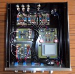
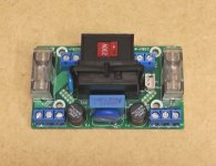
@Gideon, there is indeed a dedicated external DC protection circuit. Those relays on the main PCB are not dedicated for DC detection, but are energized via a delay circuit when it is powered on (controlled by CD4020). This way you do not get those power on 'spikes'. Thus I followed the advice of P-A: "Most users rely on internal protection circuits but I've added a separate protection against DC voltage on the amplifier output using an output relay with a protection circuit." Better safe than sorried eh, this thing has to last a lifetime! 😀
In addition there is another relay on the main PCB that I could use for switching it into standby. It would be cool if I could think of something via a remote control, but that is for later 🙂.
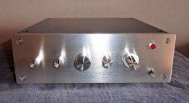
Looks wonderful, Project 16. The circuit boards appear to be home made with care and attention to detail. Do you have schematics to share, and may I ask where you got the case from?
Ranchu32 thank you!
Yes cards are designed and made by me. I think AOP better than NE5532 must provide more.
I'll make an archive with original articles (in French) and my files (pdf, gerbers, etc ...) and send it to you as soon as possible.
I took the case here:
Botier DIY aluminium Noir pour amplificateur 215x228x70mm - Audiophonics
🙂
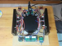
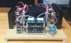
Reference-class integrated amplifier named "A1"
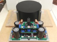
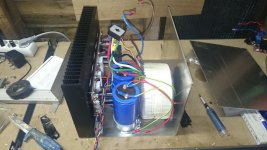
Almost three years has been taken for planning, designing and completing building this amplifier. It is named "A1" as a reference-class integrated amplifier delivering 100W per channel. The final work of casing still remains. However, I put together most of the modules making up the amplifier on a MDF board to listen to music.
The amplifier features as follows:
- a type of integrated amplifier made up of modules performing a specific function
- (not shown in the photo) operates as a power amplifier when the internal pre-amplifier is bypassed via a mode selecting switch
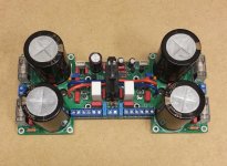
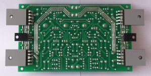
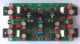
- the power amplifier module based on the Leach power amplifier acclaimed by amplifier DIYers all over the world, with the folowing additional improvements
> ON Semi's Thermaltrak transistors of NJL3281 and NJL1302 with built-in a bias diode instead of popular MJ15000 series transistors, which enable dynamic temperature compensation response, and stable and easier construction
> a circuit of DC offset adjustment added
> Ripple eater circuit for the power of the input stage to be affected less adversely by ripple of the output stage
- power on/off and volume adjustment by manual or remote control
Almost three years has been taken for planning, designing and completing building this amplifier. It is named "A1" as a reference-class integrated amplifier delivering 100W per channel. The final work of casing still remains. However, I put together most of the modules making up the amplifier on a MDF board to listen to music.
The amplifier features as follows:
- a type of integrated amplifier made up of modules performing a specific function
- (not shown in the photo) operates as a power amplifier when the internal pre-amplifier is bypassed via a mode selecting switch
- the power amplifier module based on the Leach power amplifier acclaimed by amplifier DIYers all over the world, with the folowing additional improvements
> ON Semi's Thermaltrak transistors of NJL3281 and NJL1302 with built-in a bias diode instead of popular MJ15000 series transistors, which enable dynamic temperature compensation response, and stable and easier construction
> a circuit of DC offset adjustment added
> Ripple eater circuit for the power of the input stage to be affected less adversely by ripple of the output stage
- power on/off and volume adjustment by manual or remote control
Attachments
-
 20151021_102439.jpg319.5 KB · Views: 601
 -
 20151021_101453.jpg222.8 KB · Views: 548
 -
 20151021_022151.jpg176.5 KB · Views: 519
 -
 20151021_023856.jpg371.9 KB · Views: 502
 -
 20151021_022706.jpg127.2 KB · Views: 526
 -
 20160409_142225_2.jpg253 KB · Views: 600
 -
 20160409_141506_2.jpg270 KB · Views: 685
 -
 20160411_160836.jpg353.2 KB · Views: 1,241
 -
 20160411_160723_2.jpg238.6 KB · Views: 1,249
 -
 20160411_132431_2.jpg268.4 KB · Views: 1,288
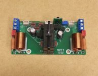
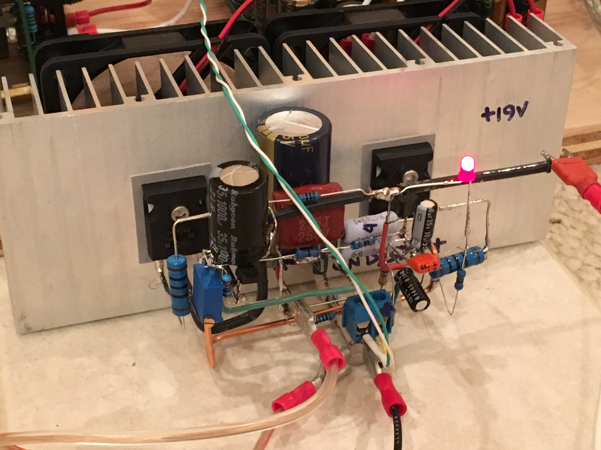
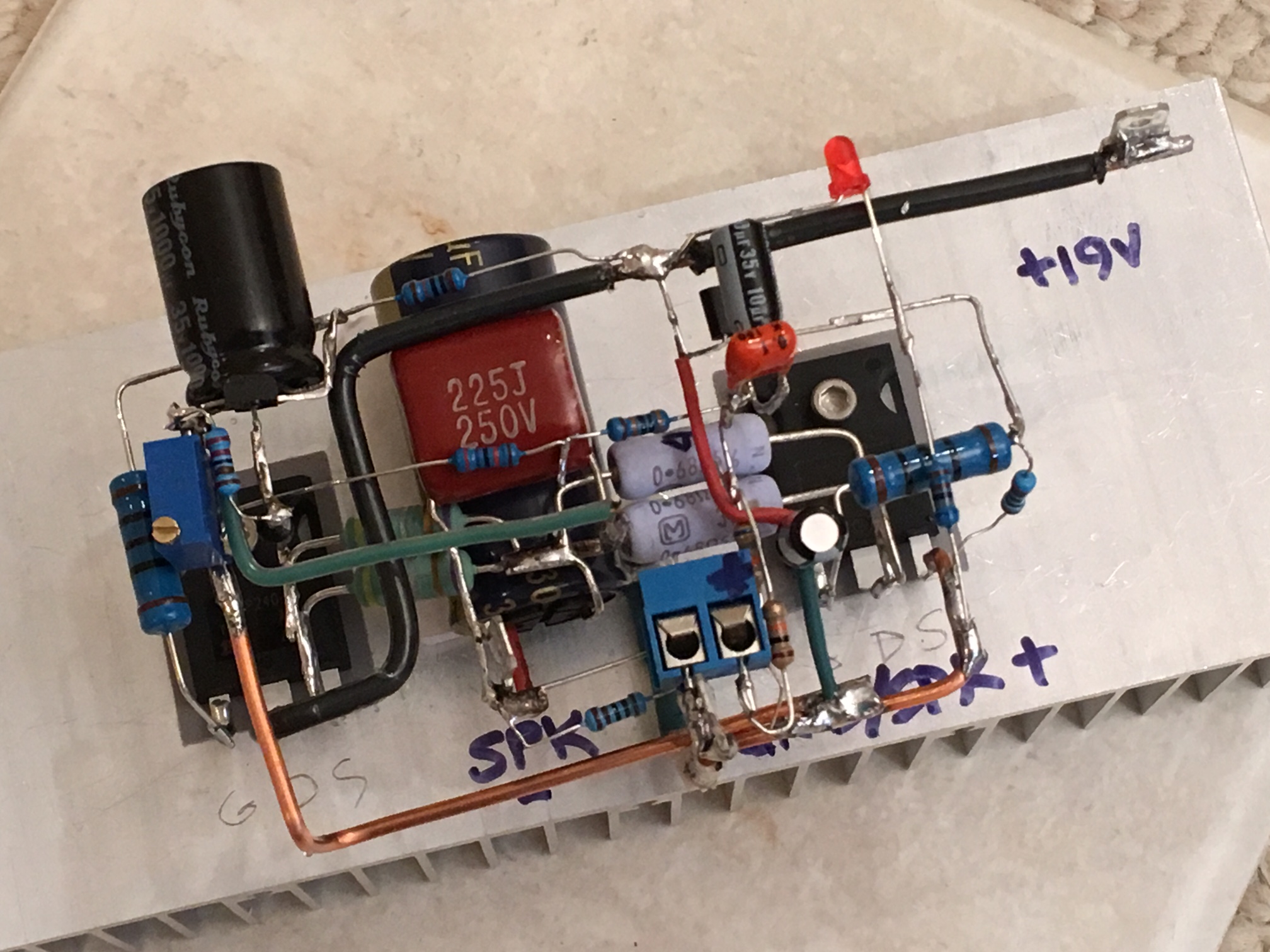
The circuits for soft start and speaker protection are provied as well.
Its sequence is power on => soft start relay turning on in 2 seconds => speaker protection relay turning on in 3 seconds.
Transistors used are as follows;
Input stage - 2SA970-GR/2SC2240-GR by Toshiba, hfe of which is matched in pairs within 2%
Second stage for pre-drive and drive - 2SA970-GR/2SC2240-GR and 2SA1930/2SC5171 by Toshiba, hfe of which is matched in pairs within 3%
Output stage - NJL1302/NJL3281 by ON Semi
Last edited:

Hello Project16,
Thanks for your having interest in my amp.
Regeading description of the sound, it's not easy to do it because the sound might be more or less different varied depending on the system configured with the amplifier, such as speakers or source gears. Nevertheless, the Leach amp is thought to be characterized by clearness and brightness.
My amp, as an integrated amp, is equipped with an pre-amp using AD8597 (dual type of AD797) and LME49600.
The gears combined with the amp are as follows;
Speakers: (Main) Triangle's Zerius 202, and (Sub) DIY speaker using Scanspeak's R2604/83200 and 15W/8530K00
DAC: DIY one using WM8741 and Combo384 DDC, which can play DSD source as well
How about the sound in my system?
High freq sounds clear and open, mid is rich and thick and bass is tight and solid.
Above all, the amp delivers harmonized and well balanced sound and is capable to drive speakers well and powerfully.
I'm so a lot satisfied with my amp.


 Please try and attach pictures directly to the forum.
To add a photo, files or non standard files.
First click "go advanced" in the box below the "quick reply" message box. Doesn't matter if you decide half way through a message to do that, it carries it forward.
Then click "Manage attachments". Maximise the new Window so that you can see all the text.
Click browse in the first box at the top and find your picture. Repeat for any more pictures.
Click upload... a message appears "uploading"
When complete the files will show as being attached. Now click the small text that says "close this window"
The pictures should now be attached and when you submit your post they will appear.
Make sure your pics aren't too big, a couple of 100k is plenty, and many members object when they are massive and it alters the margins
It tells you in the attachments window what max sizes are allowed.
If you want to attach a file that has a non standard format for example excel, circuit simulation etc then try putting the files in a zipped folder and attaching that.

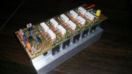
JLH 10 Watt class A Silicon Carbide


A couple of pics of the amplifier posted in solid state, the are schematics there.
A couple of pics of the amplifier posted in solid state, the are schematics there.

- Home
- Amplifiers
- Solid State
- Post your Solid State pics here