hmm i still want to try smaller cylinders. since i believe there is where the dip can be made smaller, it will hurt the low end 🙁 but hell. if you make them tall thats not a problem.. but it might be a cost problem in the magnet department 🙂 we will see.
about the PAPERS i tried. everything under 120 grams can reach 18-20khz. be it with humps and dips. everything above that or the use of excessive glue or epoxy will result in early drop off.
about the PAPERS i tried. everything under 120 grams can reach 18-20khz. be it with humps and dips. everything above that or the use of excessive glue or epoxy will result in early drop off.
Well it seems that the measurements from the newspaper surprise wasnt accurate or somethings was not good. I measured 10 times and get the same dissapointing result: that the newspaper surprise wasnt effective at all. Will try something different today and will see what happends.
SOME MORE HINTS:
1. The magnets:
*Should they be bigger or smaller in lenght?
Smaller could be costly to acieve the same strenght, but longer could be cheaper if they achieve the same force togheter.
*should they be taller or thinner?
NA (i dont have funds for buying magnets again)
*should they be weaker or stronger?
Stronger it will ad some dB but if the cilinders are not proprely damped and designed those dB's could drive you insane because of the nasty resonances amplified. Also stronger magnets will add dollars in plus to the metal plates (more thicker,or other steel ads more money to the count).
2. Metal plates:
*A very important thing that nobody answered yet: should the plates be 2cm+1cm width so that the flux would be more concentrated or other dimensions like 2+2cm would be also good?
I use the second solution with 2+2cm width because i seen that Wrine's 3cm version bended at 3mm gap. Normally the gap is 4mm, but because i used bigger plates i got 3mm gap without bending.
*what material to use for the plates?
A37 french steel was used in the original design.
AISI 1018 was also used with succes.
Romanian equivallent is OLC15X.
We use colld rolled steel now with succes and i think that with weakened magnets like n42,n38 standard AISI1017, AISI 1018 steel can be used also.
It seems that a larger quantity of carbon diminishez the force and lesser carbon improves force further but saturates more easier. So it must be just as its needed, not too much nore too little quantity of carbon.
3. The gap:
*2,3 or 4mm?
4mm for n48 magnets its perfect, smaller gap could bend the steel..
3mm ads some dB and its the limit of suportability because you can barely keep the coil centered, and as it is the coil could bend from humidity and rub on the plates causing distorsions easily and eventually take the output trannies to their graves as they did to mine .
2mm doesnt add to much stuff, its very hard to center and keep centered the coil. Also if the coil bends only a little bit disaster will strike.
Here we have also a testimony from our colleague tubegeek974:
"PS i use neo magnets from china and 3mm gap on one loudspeaker then tryied 2MM on the other with not mutch more improvements in efficiency but lots of sorrows for centering the bobin!"
4. The coil:
*single sided or double sided? SERIES OR PARALEL? PARALELLED PHASED, OR ANTI PHASED?
NA (will test these soon)
*Copper or Al?
I found that wirewound copper its very painfull and exhausting and found allot of problems to bonding and keeping it flat..
Flexible copper pcb is a good and very fast sollution, but still too heavy. If it were for me i woul search for a coil made from flexible band that was used in the old walkmans (for the screens and push comands).
For the moment diy hand made Al coils are the winners. They are light, flat, easy to bond and have good contact with the cilinders and now we have flux to solder Al (thanks Wrine).
Wrine used here a laminated AL coil made as found in the cassette players (walkmans) with succes. (Wrine can tell us more about this if he wants)
*overhung or underhung?
NA (will test this soon)
5. The paper (what kind was tested? impregnated?speacial treated)
I use The Canson paper named "CA" at 120gr/sqm with succes. To prevent the coil from bending you need to add laqueur (allot of it) on the coil to saturate the paper, this will allso soften some dips and peaks.
Wrine: "about the PAPERS i tried. everything under 120 grams can reach 18-20khz. be it with humps and dips. everything above that or the use of excessive glue or epoxy will result in early drop off."
6. The cilinders (dims, diams, shapes)
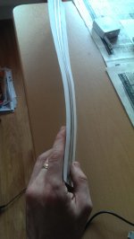
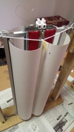
The optimum dimensions for my 50 cm ruban are 34cm*51.5cm per sheet (cilinder) to make them round or butterfly and will give you a 4.5cm per half cilinder diameter.
Shapes: well, the round one isnt better, nor best, the shape has to be between butterfly and round because making the cills too round will make them rub on each other and atenuate hights and too butterfly will increase rigidity too much and will dampen unwanted and wanted sounds too much. So its has to bee between them.
Making the coil smaller and cilinders bigger will definetly increase lows but will decrease hights so we have to be carefull here. Wrine is testing this theory right now and could tell us more if he wants.
Wrine tested a version of ruban with a cilinder cuted down, and just one active, but didnt measure good (see the posts behind), so this way is a no go.
7. The cuts:
* First of all you have to make the cuts on the interior of the coil to lower the overall mass of the coil and for increasing the hights (for me 20pcs of 8 mm diam rounded cuts inside the coil did the magic).
* make the coil smaller with 1 cm and then centrate the coil so that you have exactly 5mm above and 5 mm bellow; this will leave the coil move more freely in the top and bottom, lower the mass and make the sound more fuller, more relaxed (subjectively speaking); this will also separate the rigid portion of the cilinders (where you have the hinges or elastics bolted) from the coil thats why i heard what i sayed "make the sound more fuller, more relaxed (subjectively speaking)".
* The exterior of the cilinders:
- i have tested rectangular and triangular cuts and the winner is definetly the triangular shape cuts;
- the bigger they are the better, BUT if you make them too long or large you will add a sweet spot in the listening area and they will decrease the integrity of the coil and could bend as i experienced on the side where the BIG cuts where made.
Tested and found out this:
The best from all of them is the CLASSIC variant with small cuts, and you cand see in the "VS" graphs why (there you will find the best measures from each).
Tested so far 24cuts (75% and 50% deep), 12cuts(50%and 30% deep), 10cuts (50% and 30% deep) and 10 rectangular cuts (4cm*5mm and 2cm*5mm~5 to10% cutted down from the overall speaker surface) on each cilinder on each syde.
Conclusion: the cuts have to be not higher than the 30% wich means 5.5cm hight in the active area, and no more or less than 2.2cm base lenght (when they are cutted they remain like a equilaterall triangles like in the pic with the membrane bellow) and NO MORE THAN 10 PCS. The base of the triangles has to be equal with the space between the cuts . If you do them higher then the coil tends to bend, if you make them with the base bigger (more than 2.2cm) or make more cuts than 10 not only that will make the coil bend but this will favorise the peaks, dips and distorsions, and i think this is definetly has to do to the fact that you make the space between the cuts smaller, and this space linearise the frecv resp and dampens the peaks.
8. Suspensions
Tested yesterday:
"The elastic version has bigger dips than the hinges. The dinamics are the same (subjectivelly)and the sensitivity is a tiny bit more on the elastics but not for going this path because the dips rise higher even where you dont expect. So this aspect is solved for me. "
Elastics are a no go but i will love to use them. Today i will buy some rigid versions of elastics to test even further. But for now hinges are the winners.
If you want to go with the elastics version (because its easyier to change the membranes and recenter the coil in the future) i've tested and the finall conclusion is:
The softer the elastic is, the higher you go with the peaks and even higher with distorsion. The more tensionned you add to it, the dist goes down to almost half..
Another important aspect is that when tensionning the elastics more, the sounds comming from insyde the cuts vs between the cuts are almost the same (in a good way), except at the hights where each "covers" the other abit (the sounds from insyde and between the cuts).
Another aspect is that the ropes are a NO GO because they dont keep the coil in place at high peaks and large movements.
Thinner elastics vs thicker ones: the thinner the elastic the weaker the strenght=the higher the distortions. I now use a big elastic composed from 8 small elastics wich was the best for me..
9. Glue used
The best combo for me was first add laqueur to all the coil with the cilinder and all the other cilinder in layers till saturating the paper, then add dots of super glue on the coil like a square on the edges of the coil and dots of super glue between the round cuts inside the coil; bond the cilinders toghether fast and put a big heavy box on it and let it dry for two hours, and then 5 mins of hair drier hot air blown on it and let it cool 30min to 1hour in an opened space. (this is the method that i used)
10. Dampening
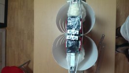
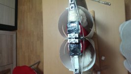
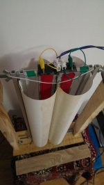
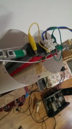
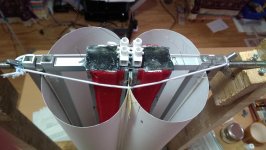
I added only medicinal cotton inside the cilinders but only between the plates and the lateralls wich bonds the paper of each cilinders together (as seen in the pics).
The cottone dampening from insyde must be insyde because the peaks that you see from my measurements (except those from 11khz to18 khz) are even higher and larger with no dampening. So the adennum of the cottone dampening insyde is very good.
Another dampening is the adenum of double adhesive tape directly onto the plates and on top of that a cottone sheet on each plate from a 100% cotton T-shirt for dampening the internall resonances (the red thing applyed onto the plates, as seen in the pics).
Also, two layers of laqueur (50% laq added from where the cilinders meet to outsyde, COMBINED WITH THE "SMALL CUTS" so that will not resonate) smoothens the overall frecv response and enlarges the sweets spot.
This is what i found today. If i think more deeper now i dont want to try to measure the ruban with a cilinder bigger and the other smaller because the smaller one will not emit hights anymore wich is a consequence for making it too rigid..
"
You can also add what you found here Wrine.
Cheers
Sergiu
Ps: I bolted with red what i still have to test.
Wrine please add you findings too. Please bold with red the things that we should test, because i think i forgoted something.. I would apreciate it very much.
1. The magnets:
*Should they be bigger or smaller in lenght?
Smaller could be costly to acieve the same strenght, but longer could be cheaper if they achieve the same force togheter.
*should they be taller or thinner?
NA (i dont have funds for buying magnets again)
*should they be weaker or stronger?
Stronger it will ad some dB but if the cilinders are not proprely damped and designed those dB's could drive you insane because of the nasty resonances amplified. Also stronger magnets will add dollars in plus to the metal plates (more thicker,or other steel ads more money to the count).
2. Metal plates:
*A very important thing that nobody answered yet: should the plates be 2cm+1cm width so that the flux would be more concentrated or other dimensions like 2+2cm would be also good?
I use the second solution with 2+2cm width because i seen that Wrine's 3cm version bended at 3mm gap. Normally the gap is 4mm, but because i used bigger plates i got 3mm gap without bending.
*what material to use for the plates?
A37 french steel was used in the original design.
AISI 1018 was also used with succes.
Romanian equivallent is OLC15X.
We use colld rolled steel now with succes and i think that with weakened magnets like n42,n38 standard AISI1017, AISI 1018 steel can be used also.
It seems that a larger quantity of carbon diminishez the force and lesser carbon improves force further but saturates more easier. So it must be just as its needed, not too much nore too little quantity of carbon.
3. The gap:
*2,3 or 4mm?
4mm for n48 magnets its perfect, smaller gap could bend the steel..
3mm ads some dB and its the limit of suportability because you can barely keep the coil centered, and as it is the coil could bend from humidity and rub on the plates causing distorsions easily and eventually take the output trannies to their graves as they did to mine .
2mm doesnt add to much stuff, its very hard to center and keep centered the coil. Also if the coil bends only a little bit disaster will strike.
Here we have also a testimony from our colleague tubegeek974:
"PS i use neo magnets from china and 3mm gap on one loudspeaker then tryied 2MM on the other with not mutch more improvements in efficiency but lots of sorrows for centering the bobin!"
4. The coil:
*single sided or double sided? SERIES OR PARALEL? PARALELLED PHASED, OR ANTI PHASED?
NA (will test these soon)
*Copper or Al?
I found that wirewound copper its very painfull and exhausting and found allot of problems to bonding and keeping it flat..
Flexible copper pcb is a good and very fast sollution, but still too heavy. If it were for me i woul search for a coil made from flexible band that was used in the old walkmans (for the screens and push comands).
For the moment diy hand made Al coils are the winners. They are light, flat, easy to bond and have good contact with the cilinders and now we have flux to solder Al (thanks Wrine).
Wrine used here a laminated AL coil made as found in the cassette players (walkmans) with succes. (Wrine can tell us more about this if he wants)
*overhung or underhung?
NA (will test this soon)
5. The paper (what kind was tested? impregnated?speacial treated)
I use The Canson paper named "CA" at 120gr/sqm with succes. To prevent the coil from bending you need to add laqueur (allot of it) on the coil to saturate the paper, this will allso soften some dips and peaks.
Wrine: "about the PAPERS i tried. everything under 120 grams can reach 18-20khz. be it with humps and dips. everything above that or the use of excessive glue or epoxy will result in early drop off."
6. The cilinders (dims, diams, shapes)
The optimum dimensions for my 50 cm ruban are 34cm*51.5cm per sheet (cilinder) to make them round or butterfly and will give you a 4.5cm per half cilinder diameter.
Shapes: well, the round one isnt better, nor best, the shape has to be between butterfly and round because making the cills too round will make them rub on each other and atenuate hights and too butterfly will increase rigidity too much and will dampen unwanted and wanted sounds too much. So its has to bee between them.
Making the coil smaller and cilinders bigger will definetly increase lows but will decrease hights so we have to be carefull here. Wrine is testing this theory right now and could tell us more if he wants.
Wrine tested a version of ruban with a cilinder cuted down, and just one active, but didnt measure good (see the posts behind), so this way is a no go.
7. The cuts:
* First of all you have to make the cuts on the interior of the coil to lower the overall mass of the coil and for increasing the hights (for me 20pcs of 8 mm diam rounded cuts inside the coil did the magic).
* make the coil smaller with 1 cm and then centrate the coil so that you have exactly 5mm above and 5 mm bellow; this will leave the coil move more freely in the top and bottom, lower the mass and make the sound more fuller, more relaxed (subjectively speaking); this will also separate the rigid portion of the cilinders (where you have the hinges or elastics bolted) from the coil thats why i heard what i sayed "make the sound more fuller, more relaxed (subjectively speaking)".
* The exterior of the cilinders:
- i have tested rectangular and triangular cuts and the winner is definetly the triangular shape cuts;
- the bigger they are the better, BUT if you make them too long or large you will add a sweet spot in the listening area and they will decrease the integrity of the coil and could bend as i experienced on the side where the BIG cuts where made.
Tested and found out this:
The best from all of them is the CLASSIC variant with small cuts, and you cand see in the "VS" graphs why (there you will find the best measures from each).
Tested so far 24cuts (75% and 50% deep), 12cuts(50%and 30% deep), 10cuts (50% and 30% deep) and 10 rectangular cuts (4cm*5mm and 2cm*5mm~5 to10% cutted down from the overall speaker surface) on each cilinder on each syde.
Conclusion: the cuts have to be not higher than the 30% wich means 5.5cm hight in the active area, and no more or less than 2.2cm base lenght (when they are cutted they remain like a equilaterall triangles like in the pic with the membrane bellow) and NO MORE THAN 10 PCS. The base of the triangles has to be equal with the space between the cuts . If you do them higher then the coil tends to bend, if you make them with the base bigger (more than 2.2cm) or make more cuts than 10 not only that will make the coil bend but this will favorise the peaks, dips and distorsions, and i think this is definetly has to do to the fact that you make the space between the cuts smaller, and this space linearise the frecv resp and dampens the peaks.
8. Suspensions
Tested yesterday:
"The elastic version has bigger dips than the hinges. The dinamics are the same (subjectivelly)and the sensitivity is a tiny bit more on the elastics but not for going this path because the dips rise higher even where you dont expect. So this aspect is solved for me. "
Elastics are a no go but i will love to use them. Today i will buy some rigid versions of elastics to test even further. But for now hinges are the winners.
If you want to go with the elastics version (because its easyier to change the membranes and recenter the coil in the future) i've tested and the finall conclusion is:
The softer the elastic is, the higher you go with the peaks and even higher with distorsion. The more tensionned you add to it, the dist goes down to almost half..
Another important aspect is that when tensionning the elastics more, the sounds comming from insyde the cuts vs between the cuts are almost the same (in a good way), except at the hights where each "covers" the other abit (the sounds from insyde and between the cuts).
Another aspect is that the ropes are a NO GO because they dont keep the coil in place at high peaks and large movements.
Thinner elastics vs thicker ones: the thinner the elastic the weaker the strenght=the higher the distortions. I now use a big elastic composed from 8 small elastics wich was the best for me..
9. Glue used
The best combo for me was first add laqueur to all the coil with the cilinder and all the other cilinder in layers till saturating the paper, then add dots of super glue on the coil like a square on the edges of the coil and dots of super glue between the round cuts inside the coil; bond the cilinders toghether fast and put a big heavy box on it and let it dry for two hours, and then 5 mins of hair drier hot air blown on it and let it cool 30min to 1hour in an opened space. (this is the method that i used)
10. Dampening
I added only medicinal cotton inside the cilinders but only between the plates and the lateralls wich bonds the paper of each cilinders together (as seen in the pics).
The cottone dampening from insyde must be insyde because the peaks that you see from my measurements (except those from 11khz to18 khz) are even higher and larger with no dampening. So the adennum of the cottone dampening insyde is very good.
Another dampening is the adenum of double adhesive tape directly onto the plates and on top of that a cottone sheet on each plate from a 100% cotton T-shirt for dampening the internall resonances (the red thing applyed onto the plates, as seen in the pics).
Also, two layers of laqueur (50% laq added from where the cilinders meet to outsyde, COMBINED WITH THE "SMALL CUTS" so that will not resonate) smoothens the overall frecv response and enlarges the sweets spot.
This is what i found today. If i think more deeper now i dont want to try to measure the ruban with a cilinder bigger and the other smaller because the smaller one will not emit hights anymore wich is a consequence for making it too rigid..
"
You can also add what you found here Wrine.
Cheers
Sergiu
Ps: I bolted with red what i still have to test.
Wrine please add you findings too. Please bold with red the things that we should test, because i think i forgoted something.. I would apreciate it very much.
Well i've been busy this weekend,
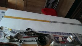
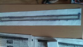
Been making another two variants:
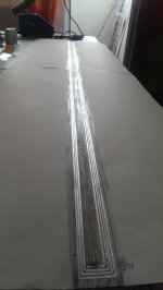
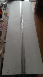
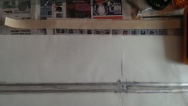
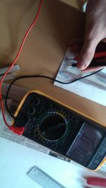
1. Coils onto the cils, double syded,underhung, 3turn at 1.8 mm at 7 ohms, bonded toghether with dozble adhesive tape and laq.
2. Coils onto a bigger paper former,double syded, underhung,3.5 turns per coil (the0.5 turn its strategically there),8ohm, bonded togheter with laq and super glue.
3. Tested on classic: one cilinder shrinked (one half cil has 3 cm and the other cil has on a half 4cm), and both cils shrinked at 3cm per half (cant go lower than this).
Will post measures tomorow.
Cheers
Sergiu
Been making another two variants:
1. Coils onto the cils, double syded,underhung, 3turn at 1.8 mm at 7 ohms, bonded toghether with dozble adhesive tape and laq.
2. Coils onto a bigger paper former,double syded, underhung,3.5 turns per coil (the0.5 turn its strategically there),8ohm, bonded togheter with laq and super glue.
3. Tested on classic: one cilinder shrinked (one half cil has 3 cm and the other cil has on a half 4cm), and both cils shrinked at 3cm per half (cant go lower than this).
Will post measures tomorow.
Cheers
Sergiu
Attachments
-
 IMAG0152.jpg963 KB · Views: 363
 -
 IMAG0151.jpg818.4 KB · Views: 335
 -
 IMAG0157.jpg947.1 KB · Views: 322
 -
 IMAG0154.jpg366.9 KB · Views: 306
 -
 IMAG0161.jpg381.3 KB · Views: 295
 -
 IMAG0158.jpg345.7 KB · Views: 176
 -
 IMAG0159.jpg378 KB · Views: 187
 -
 IMAG0160.jpg931.2 KB · Views: 189
 -
 IMAG0164.jpg353 KB · Views: 212
 -
 IMAG0163.jpg345.2 KB · Views: 214
Hi, I put together a rubanoide or something like it... but with magnet wire and not Alu foil. With normal office paper and 32 AWG, around 28 cm long but observed a drop off after 11KHz. The undamped edges of the paper was also a source of concern as you can see in the video.
https://www.youtube.com/watch?v=AoOkLsnp4eg
The horizontal dispersion is really good. It has been remarked upon by Wrine and others but the space from such a small speaker is very unrealistic, filling the room.
Few things I would like to know... is fibre glass a good option instead of paper? There is 48 gsm fibre glass available for a good price here. 2 layers of it with epoxy and 40 awg wire will be light enough to reach 16-18 Khz ? Could some one also shed some light on what lacquer does to paper?
Now plann
Hi, I put together a rubanoide or something like it... but with magnet wire and not Alu foil. With normal office paper and 32 AWG, around 28 cm long but observed a drop off after 11KHz. The undamped edges of the paper was also a source of concern as you can see in the video.
https://www.youtube.com/watch?v=AoOkLsnp4eg
The horizontal dispersion is really good. It has been remarked upon by Wrine and others but the space from such a small speaker is very unrealistic, filling the room.
Few things I would like to know... is fibre glass a good option instead of paper? There is 48 gsm fibre glass available for a good price here. 2 layers of it with epoxy and 40 awg wire will be light enough to reach 16-18 Khz ? Could some one also shed some light on what lacquer does to paper?
Now plann
Hi ayaflo,
I'm glad you tryied it.. I have to say that fiber glass is too heavy and dampens hights too much, BUT if you want to try it i strongly recommend using the cuts because it will make the coil lighter here and there and will compensate for some of that weight.
Also i would not recomend a wire heavyier than 0.18~0.2mm CuEm (dims with insulation included) and this will give you 40W 0.18mm to max 80w for 0.2mm sinus.
The best till now is still paper as we tested in our earlyer tests; but the best of all is Tedlar (tedlar | eBay), then Mylar, Kapton and the last is paper with laq aded of course from 120gr/sqm and down.
Cheers
Sergiu
Ps: i want to confess that winding the coil with copper by hand is a really pain in the A**... but you should know that Al coils are easyier to do, and goes way higher than 20khz, and now i can make a double syded coil in 1.5~2hours and it only takes a little practise.
Last edited:
Now the measurements from one cil smaller (3cm per half) and the other bigger(4cm per half) and then both shrinked at 3 cm per half.
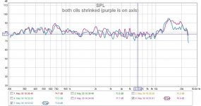
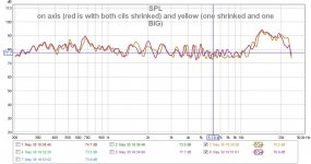
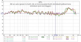
The conclusion as seen in the graphs, is that both cils shrinked gives a smoother overall frecv response BUT doesnt go up to 24KHZ in stead i goes up to 20khz and rolls off smoothely...
When listened to both variants, to my ears the "both cils shrinked" variant sounds restrained wich gives the impression that the membrane has harden too much... The "one cil smaller then the other" vers wins the bet to me Wrine.
I dont see any of these to be used in the future because they dont resolve our problem and the version with one cill bigger and the other smaller its abit harder to make and i can barelly keep the coil into the gap without rubbing.
Attachments
-
 one small and one BIG.jpg345.2 KB · Views: 169
 -
 small membrane.jpg353 KB · Views: 142
 -
 both cils shrinked (purple is on axis).jpg116.6 KB · Views: 158
 -
 on axis (red is with both cils shrinked) and yellow (one shrinked and one BIG).jpg121.8 KB · Views: 138
 -
 REd(on axis)+green(off).jpg117.5 KB · Views: 111
 -
 All on axis (green is both cils at 4cm+purple=both shrinked+yellow=one shrinked and one bigger).jpg128.9 KB · Views: 112
 -
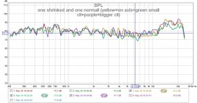 one shrinked and one normall (yellow=on axis+green small cil+purple=bigger cil).jpg127.8 KB · Views: 116
Those measurements looks awesome... I want to know what Lacquer does to paper
Thanks,
The laq its buyed from a local shop and its used for winding trafos. It hardens very fast if thin layers are applyier (max 30sec)..
NOW this is what i was talking yesterday here (http://www.diyaudio.com/forums/plan...on-speaker-different-kind-77.html#post4731081). This is the first version with the double adhesive tape and laq.
This ruban HAS NOTHING ADED YET (no internall cotton, no laq,no cuts) and its pretty promicing.
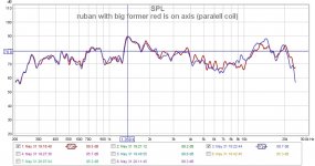
For me its a battle is between PARALEL REVERSED polarity and SERIES REVERSED polarity (wich has the best bass till now).
To me the winner is the double coil version, in series, in reverse polarity (has better bass, smoother peaks) and even with nothing on it (damping or whatsoever) can still compete with the "classic vers" as seen in "ON AXIS (purple=double coil)" where RED WAS "classic vers" with single coil.
Till now this is the best bass response that i ever auditioned on a ruban till this date. The voice is abit damped for this ruban, BUT this can be corrected easily with some laq. 🙂
This seems to be our sollution to our problems Wrine, a double sided coil.
Cheers
Sergiu
This ruban HAS NOTHING ADED YET (no internall cotton, no laq,no cuts) and its pretty promicing.
For me its a battle is between PARALEL REVERSED polarity and SERIES REVERSED polarity (wich has the best bass till now).
To me the winner is the double coil version, in series, in reverse polarity (has better bass, smoother peaks) and even with nothing on it (damping or whatsoever) can still compete with the "classic vers" as seen in "ON AXIS (purple=double coil)" where RED WAS "classic vers" with single coil.
Till now this is the best bass response that i ever auditioned on a ruban till this date. The voice is abit damped for this ruban, BUT this can be corrected easily with some laq. 🙂
This seems to be our sollution to our problems Wrine, a double sided coil.
Cheers
Sergiu
Attachments
-
 FIRST series coil (black=on axis) POLARITY REVERSED.jpg116.7 KB · Views: 96
 -
 FIRST PARALEL reversed pol AND dark green is on axis.jpg121.6 KB · Views: 105
 -
 FIRST paralel (green=on axis).jpg118 KB · Views: 125
 -
 FIRST series coil (purple=on axis).jpg123.2 KB · Views: 91
 -
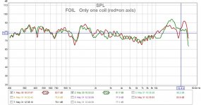 FOIL Only one coil (red=on axis).jpg120.4 KB · Views: 93
 -
 ON AXIS (dark green=paralled;dark purple=series); OFF axis (white green=paralled;white blue=seri.jpg138.6 KB · Views: 103
 -
 ON AXIS (purple=double coil).jpg116.8 KB · Views: 96
 -
 ON AXIS (red=single coil+green=rev paralel+purple=rev series).jpg132.4 KB · Views: 97
SOME MORE HINTS. I will write them down because later i will forget..):
1. The magnets:
*Should they be bigger or smaller in lenght?
Smaller could be costly to acieve the same strenght, but longer could be cheaper if they achieve the same force togheter.
*should they be taller or thinner?
NA (i dont have funds for buying magnets again)
*should they be weaker or stronger?
Stronger it will ad some dB but if the cilinders are not proprely damped and designed those dB's could drive you insane because of the nasty resonances amplified. Also stronger magnets will add dollars in plus to the metal plates (more thicker,or other steel ads more money to the count).
2. Metal plates:
*A very important thing that nobody answered yet: should the plates be 2cm+1cm width so that the flux would be more concentrated or other dimensions like 2+2cm would be also good?
I use the second solution with 2+2cm width because i seen that Wrine's 3cm version bended at 3mm gap. Normally the gap is 4mm, but because i used bigger plates i got 3mm gap without bending.
*what material to use for the plates?
A37 french steel was used in the original design.
AISI 1018 was also used with succes.
Romanian equivallent is OLC15X.
We use colld rolled steel now with succes and i think that with weakened magnets like n42,n38 standard AISI1017, AISI 1018 steel can be used also.
It seems that a larger quantity of carbon diminishez the force and lesser carbon improves force further but saturates more easier. So it must be just as its needed, not too much nore too little quantity of carbon.
3. The gap:
*2,3 or 4mm?
4mm for n48 magnets its perfect, smaller gap could bend the steel..
3mm ads some dB and its the limit of suportability because you can barely keep the coil centered, and as it is the coil could bend from humidity and rub on the plates causing distorsions easily and eventually take the output trannies to their graves as they did to mine .
2mm doesnt add to much stuff, its very hard to center and keep centered the coil. Also if the coil bends only a little bit disaster will strike.
Here we have also a testimony from our colleague tubegeek974:
"PS i use neo magnets from china and 3mm gap on one loudspeaker then tryied 2MM on the other with not mutch more improvements in efficiency but lots of sorrows for centering the bobin!"
4. The coil:
*single sided or double sided?
DOUBLE SIDED FOR SHURE (its the best till now from all the measurements).
SERIES OR PARALEL?
Series its best with +-+- conected and then conected in reverse (best from measurements) .
*Copper or Al?
I found that wirewound copper its very painfull and exhausting and found allot of problems to bonding and keeping it flat..
Flexible copper pcb is a good and very fast sollution, but still too heavy. If it were for me i woul search for a coil made from flexible band that was used in the old walkmans (for the screens and push comands).
For the moment diy hand made Al coils are the winners. They are light, flat, easy to bond and have good contact with the cilinders and now we have flux to solder Al (thanks Wrine).
Wrine used here a laminated AL coil made as found in the cassette players (walkmans) with succes. (Wrine can tell us more about this if he wants)
*overhung or underhung?
Underhung its best (those dB in plus will compensate for conecting the coils in series (if two coils are used in double syded mode).. It measured very good.
5. The paper (what kind was tested? impregnated?speacial treated)
I use The Canson paper named "CA" at 120gr/sqm with succes. To prevent the coil from bending you need to add laqueur (allot of it) on the coil to saturate the paper, this will allso soften some dips and peaks.
Wrine: "about the PAPERS i tried. everything under 120 grams can reach 18-20khz. be it with humps and dips. everything above that or the use of excessive glue or epoxy will result in early drop off."
6. The cilinders (dims, diams, shapes)
The optimum dimensions for my 50 cm ruban are 34cm*51.5cm per sheet (cilinder) to make them round or butterfly and will give you a 4.5cm per half cilinder diameter.
Shapes: well, the round one isnt better, nor best, the shape has to be between butterfly and round because making the cills too round will make them rub on each other and atenuate hights and too butterfly will increase rigidity too much and will dampen unwanted and wanted sounds too much. So its has to bee between them.
Making the coil smaller and cilinders bigger will definetly increase lows but will decrease hights so we have to be carefull here. Wrine is testing this theory right now and could tell us more if he wants.
Wrine tested a version of ruban with a cilinder cuted down, and just one active, but didnt measure good (see the posts behind), so this way is a no go.
I tested two versions, one with a cil shrinked and the other bigger and another version with both cils shrinked and the conclusion from measurements are:
"Now the measurements from one cil smaller (3cm per half) and the other bigger(4cm per half) and then both shrinked at 3 cm per half.
The conclusion as seen in the graphs, is that both cils shrinked gives a smoother overall frecv response BUT doesnt go up to 24KHZ in stead i goes up to 20khz and rolls off smoothely...
When listened to both variants, to my ears the "both cils shrinked" variant sounds restrained wich gives the impression that the membrane has harden too much... The "one cil smaller then the other" vers wins the bet to me Wrine.
I dont see any of these to be used in the future because they dont resolve our problem and the version with one cill bigger and the other smaller its abit harder to make and i can barelly keep the coil into the gap without rubbing."
7. The cuts:
* First of all you have to make the cuts on the interior of the coil to lower the overall mass of the coil and for increasing the hights (for me 20pcs of 8 mm diam rounded cuts inside the coil did the magic).
* make the coil smaller with 1 cm and then centrate the coil so that you have exactly 5mm above and 5 mm bellow; this will leave the coil move more freely in the top and bottom, lower the mass and make the sound more fuller, more relaxed (subjectively speaking); this will also separate the rigid portion of the cilinders (where you have the hinges or elastics bolted) from the coil thats why i heard what i sayed "make the sound more fuller, more relaxed (subjectively speaking)".
* The exterior of the cilinders:
- i have tested rectangular and triangular cuts and the winner is definetly the triangular shape cuts;
- the bigger they are the better, BUT if you make them too long or large you will add a sweet spot in the listening area and they will decrease the integrity of the coil and could bend as i experienced on the side where the BIG cuts where made.
Tested and found out this:
The best from all of them is the CLASSIC variant with small cuts, and you cand see in the "VS" graphs why (there you will find the best measures from each).
Tested so far 24cuts (75% and 50% deep), 12cuts(50%and 30% deep), 10cuts (50% and 30% deep) and 10 rectangular cuts (4cm*5mm and 2cm*5mm~5 to10% cutted down from the overall speaker surface) on each cilinder on each syde.
Conclusion: the cuts have to be not higher than the 30% wich means 5.5cm hight in the active area, and no more or less than 2.2cm base lenght (when they are cutted they remain like a equilaterall triangles like in the pic with the membrane bellow) and NO MORE THAN 10 PCS. The base of the triangles has to be equal with the space between the cuts . If you do them higher then the coil tends to bend, if you make them with the base bigger (more than 2.2cm) or make more cuts than 10 not only that will make the coil bend but this will favorise the peaks, dips and distorsions, and i think this is definetly has to do to the fact that you make the space between the cuts smaller, and this space linearise the frecv resp and dampens the peaks.
8. Suspensions
Tested yesterday:
"The elastic version has bigger dips than the hinges. The dinamics are the same (subjectivelly)and the sensitivity is a tiny bit more on the elastics but not for going this path because the dips rise higher even where you dont expect. So this aspect is solved for me. "
Elastics are a no go but i will love to use them. Today i will buy some rigid versions of elastics to test even further. But for now hinges are the winners.
If you want to go with the elastics version (because its easyier to change the membranes and recenter the coil in the future) i've tested and the finall conclusion is:
The softer the elastic is, the higher you go with the peaks and even higher with distorsion. The more tensionned you add to it, the dist goes down to almost half..
Another important aspect is that when tensionning the elastics more, the sounds comming from insyde the cuts vs between the cuts are almost the same (in a good way), except at the hights where each "covers" the other abit (the sounds from insyde and between the cuts).
Another aspect is that the ropes are a NO GO because they dont keep the coil in place at high peaks and large movements.
Thinner elastics vs thicker ones: the thinner the elastic the weaker the strenght=the higher the distortions. I now use a big elastic composed from 8 small elastics wich was the best for me..
9. Glue used
The best combo for me was first add laqueur to all the coil with the cilinder and all the other cilinder in layers till saturating the paper, then add dots of super glue on the coil like a square on the edges of the coil and dots of super glue between the round cuts inside the coil; bond the cilinders toghether fast and put a big heavy box on it and let it dry for two hours, and then 5 mins of hair drier hot air blown on it and let it cool 30min to 1hour in an opened space. (this is the method that i used)
I used double adhesive tape with laq onto the cils to bond directly the two sided coils and the cilinders toghether; the bonding was made directly onto the coil area with succes and good measurements.
10. Dampening
I added only medicinal cotton inside the cilinders but only between the plates and the lateralls wich bonds the paper of each cilinders together (as seen in the pics).
The cottone dampening from insyde must be insyde because the peaks that you see from my measurements (except those from 11khz to18 khz) are even higher and larger with no dampening. So the adennum of the cottone dampening insyde is very good.
Another dampening is the adenum of double adhesive tape directly onto the plates and on top of that a cottone sheet on each plate from a 100% cotton T-shirt for dampening the internall resonances (the red thing applyed onto the plates, as seen in the pics).
Also, two layers of laqueur (50% laq added from where the cilinders meet to outsyde, COMBINED WITH THE "SMALL CUTS" so that will not resonate) smoothens the overall frecv response and enlarges the sweets spot.
This is what i found today. If i think more deeper now i dont want to try to measure the ruban with a cilinder bigger and the other smaller because the smaller one will not emit hights anymore wich is a consequence for making it too rigid..
"
You can also add what you found here Wrine.
Cheers
Sergiu
Ps: I bolted with red what i still have to test.
I have to rectify in this post from here:
http://www.diyaudio.com/forums/plan...on-speaker-different-kind-77.html#post4731081
The coils that are bonded with double adhesive tape form 1. have 3.5 turns at 8 ohms (the half turn is aded on the interior of the coil as seen in the pics with the coils made directly onto the cils) and the second version from 2. has only 3 turns at 7 ohms and the coils are made on a bigg paper fromer as seen in the pics. Please excuse me, its because of late night posting...
Now i aded 50%laq to the membrane.
The conclusion is as usual: the double coats of laq smooths as usual from 2khz to 19khz, on axis and off axis as seen in the measurements; its gives also a little boost to the 20khz to 24khz region as well. This is directly compared with the same version only without the laq as seen in the measurements.
Now the voice doesnt seem to be dampened or restrained anymore and you can definetly hear some clear hights now (from listening tests).
Attachments


Last edited:
Here they are. I disassembled the "classic" design and assembled instead the ruban with the coil on bigger paper former. Now we have two victims, one with smaller former (double adhesive tape from earlyier measures) and one with bigher former (never tested)..
Cheers
Sergiu
Cheers
Sergiu
Attachments
Hmm i made something different today 🙂
https://youtu.be/vBx6b0o5HUs
cant go verry loud since it is very inefficient with those 1mm magnets 🙂 there is no sub used, just a noth at 1.4 khz of -8 db somehow it is efficient around that area.
https://youtu.be/vBx6b0o5HUs
cant go verry loud since it is very inefficient with those 1mm magnets 🙂 there is no sub used, just a noth at 1.4 khz of -8 db somehow it is efficient around that area.
Last edited:
Hmm i made something different today 🙂
https://youtu.be/vBx6b0o5HUs
cant go verry loud since it is very inefficient with those 1mm magnets 🙂 there is no sub used, just a noth at 1.4 khz of -8 db somehow it is efficient around that area.
Hello my friend,
Your video is not available.
Upload again please.
Cheers
Sergiu
damned it is blocked in your country
Nope its blocked only on the phones... Dont know why...
That speaker sound extrodinary. Congrats Wrine. Its a very good sound.
I now use different holster for my phone so i dont know how will my phone records. I made two vids, one its with explanations and the other is with a short melody.
Strange thing that all of my dual coil rubans have the same dip of aprox -8~-10dB around 900 to 1400Hz..
Now i'm uploading them on youtube.
Last edited:
Now here is the ruban with a huuge extended former to outsyde the cilionders..
As we can see again the two coats of laq smoothes the frecv good. I will expleain in the vids why i dont like this. Its because how its plays and because of the off axis out of phase strange sound.. (i explained this in my uploaded vids)..
As we can see again the two coats of laq smoothes the frecv good. I will expleain in the vids why i dont like this. Its because how its plays and because of the off axis out of phase strange sound.. (i explained this in my uploaded vids)..
Attachments

Ho serg, i usually remove the phone from its holster when recording. since it might block the mic.
Btw can you add the distortion graph as well? since it will tell us more whats going on.
i have some major problems 🙁 my printer is bitching about Yellow ink.. and now magenta... and soon cyan
The printer can print without using color. BUT when it cleans (witch has to be done every now and then) it purges 5 euro of ink into the waste tray, of each color. now the color sticks are aaaaalll gone and it wont print since it wanted to clean..... damned.... i bought yellow since that one was completely empty... (60 Euro) then today they came in. yeaaah replaced them and wanted to print black... it has very thin white stripes.... and i am pretty sure it is some sort of setting since i bought a new computer. and when i print a test page from the printer it self it has no stripes.. but anyhow i thought i might try a cleaning..... dumb me. Now the magenta is empty and have to replace that one before it even prints black and hopefully can fix the stripes.... god damned. and if i cant, i just wasted 180 euro on ink... since cyan is also empty..
another option is buy a new second hand Solid ink printer, witch cost 280 Euro, not even sure it has ink in it... but the ink itself is a bit cheaper at least. and the resolution is higher. hope it works as good on alumnium as this one did. but then again i wasted 120 euro on ink for the old printer (yellow and black).... i want this thing running 🙁
Last edited:
- Home
- Loudspeakers
- Planars & Exotics
- A DIY Ribbon Speaker of a different Kind