Thanks for the info. I think I will go that route too.I use cheap chinese SMPS for the heaters in several direct heating amps. No hum or noise at all. at the moment i use a fu13(813) amp to.
I run the smps with NTC resistor to slow down the startup current.
A small caveat: Beware of the SMPS's that have a specific overload protection mode, called the "fallback" or the "hickup" mode. Such ones may have difficulty starting, or even may not start at all, when facing a "cold filament".
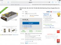
The unit I wrote found on offer, the Mean Well SP-150-12, or ... better yet, the SP-150-13,5 (13,5V) is of a different construction. It has a "Constant Current" limiting overload protection circuit. It simply does not "allow" more than 150W/12V or 150W/13,5V of current (+ some % margin) ever to flow. It acts as a current limiter.
Therefore, I was thinking that if the GU-81 draws 10,5A, then the SP-150-13,5 would be ideal. With the current limit set at somewhere around 11A, it shall act as a natural "soft start". To add on top of that, I will go with the CLC filter, with some heavy uF elko to "slower" the voltage rise time, and bypassed with some small foil uF to shunt the kHz hash frequencies, if any. The L would be the ideal solution to loose some of the excess volts that come out of the device. The rest I shall loose on the interconnecting wiring and with the trim pot.
I will go with independent units for each of the tubes. I.e. four tubes = 4 SMPS units. The 150 Watt modules are the highest of the row which come without active fan cooling. If they will be loaded to not more than 80% of the nominal power rating, then within normal ambient conditions and with appropriate air flow they supposedly do not require any forced cooling, fans or stuff.Do you have one SMPS divided for both GU81's ?
I use one SMPS for FU13(120Watt) and one for GU81(200Watt). They are without active cooling(silent). Rimple(noise) is very low 10mv at 40khz on the heater. At the output not measureble.Can you suggest any supplier ?
Do you have one SMPS divided for both GU81's ?
Attachments

A small caveat: Beware of the SMPS's that have a specific overload protection mode, called the "fallback" or the "hickup" mode. Such ones may have difficulty starting, or even may not start at all, when facing a "cold filament.
Just use NTC in serie with 12v supply. You then have softstart for cold heater. Works great.
I use one 2 ohm NTC for heater FU13 and two 2 Ohm NTC in parallel for GU81.
Ronny
Attachments

Last edited:
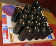
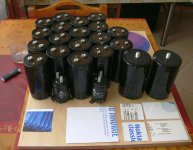
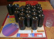
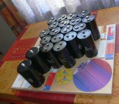
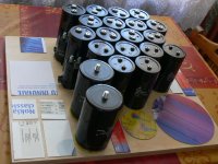
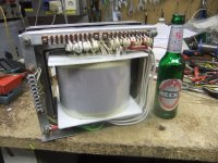
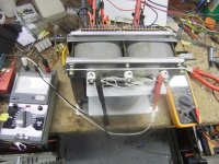
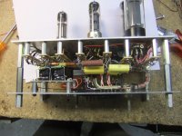
Started assembly of one of the monoblocks.
One of the element support planes (plywood).
The first of the two, the one holding the anode supply toroids,
the mercury rectifier heater toroid, the anode filter capacitors (as visualized) and some inductance to assist them …
One of the element support planes (plywood).
The first of the two, the one holding the anode supply toroids,
the mercury rectifier heater toroid, the anode filter capacitors (as visualized) and some inductance to assist them …
Attachments
Yes, but the old one was slightly haphazard / make-shift, so as to re-use some less than optimal toroidal transformers from a different project.Zjjwwa,
do you have a schematic of the power supply?
I will search for the drawing and pasted here in a little while (when I find it).
Anyways, something very similar to this initial concept:
http://hiend-audio.com/2014/08/18/low-dc-from-high-ac/
It basically uses two 1200VAC - 0VAC - 1200VAC transformers to obtain 1500V DC, but also .... 750V DC.... 🙂
For this new "V.2" version of the project, I ordered some more reasonable toroids with some extra / additional tappings, which provide for greater flexibility of use and playing around with them. Generally, the new PS will be based upon mercury rectifier tubes for the anode, rectifier tubes for the S2 ... and a small little "cheater" mechanism, so as to provide for safe start of the PS, so as not to fry the mercury rectifiers. Once I build the supply, I will most probably draw/design it.
Last edited:
Below a great link for transformers and other tube supply.
http://www.elektrodump.nl/12-transformatoren
http://www.elektrodump.nl/12-transformatoren
Attachments

This is my "old" one ...Zjjwwa,
do you have a schematic of the power supply?
(I do not know why the central ground bar ... disappeared in this rendering ... but it is there )
Attachments
Last edited:
Hi,
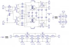
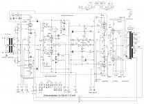
here I got another schematic with GU-81 P-P amp. Its a current projekt starting abt a year way back.
See pics below.
There still a lot of things to do, especially with the mechanics. The OPT is too heavy. It need to reinforce the chassispanel. I have only now realised what a huge task it is to build an amp of such caliber. But I started the game, and I will finished it
To do list:
Fitting the controls in the frontpanel and sockets in the backpanel.
Making a safegard circuít for the tubes, which looks after grid and plate .
currents and turns off when overloaded.
Fitting safety switches to shut off HV when open a cover while the amp is live.
Finishing the main power supply.
Cutting and drilling the side, top and bottom covers.
The amp putting out 1500W rms. It operates in P-P B2. The plate needs 2300V and 600V at the screens.
The aux mains transformer is also finished but I have currently no pics of it. Both the trafos are homewind . The opt is a SE231b core, the total weight is 34kg.
I will build the HV Power supply as a switchmode supply. It got its own housing. The amp need 0,9 A plate current at full blast. I made switchmode power supplies before, so I´m little familar with them.
The opt was the most time consuming part to make. Looking out for all necessary parts take also much time. Finally getting the core from a member of "die röhrenbude", a german tube enthusiast forum. Than I purchased all the wire, the insulation foil etc at a local trafo company. I need abt a week just only to get all the copper on the bobbin.
73
Wolfgang
Attachments

Thats real hard ware, that I like. Hope, the sound is appropriate..
Here´s my own monster amp:
2000 Watts Output at 1800V, the 60V light bulb is to indicate screen overload.
This one, I built in the 1990´s with 6xWesternElectric 715B's, cathode driver is the 5998 triode. Driver is the 5687.
Output 950 watts at 1500V plate voltage
Here´s my own monster amp:
An externally hosted image should be here but it was not working when we last tested it.
2000 Watts Output at 1800V, the 60V light bulb is to indicate screen overload.
This one, I built in the 1990´s with 6xWesternElectric 715B's, cathode driver is the 5998 triode. Driver is the 5687.
An externally hosted image should be here but it was not working when we last tested it.
Output 950 watts at 1500V plate voltage
Last edited:
My God! Do you plan to heat your house this winter with your amp? Only ONE filament need around 140W!
Thats real hard ware, that I like. Hope, the sound is appropriate..
Hi, what kind of opt is in the 2kW edition. Is it self made or custom wound at a lokal transformer shop. Please show a pic of it.
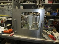
My amp is nearly finished with the mechanical work. I coming up soon with more interesting work on it.
Bugger! I forget to fit center taps on the GU-81 filamant windings of the aux mains trafo. That means another half day for the bin.🙁
73 Wolfgang DF6ZC

Self made but built to order for a transformer company near Hannover. They are doing high-voltage transformer checks with it. Only one socket blew up during 20 years period of duty. The control unit is a separate Rack containing 6 EL34 tubes.
The output transformer is a hand-wounded double 170 C-core. Our Aumann winding machine isn´t suitable for that size! If you want more Info, send me an E-Mail. I would like to see your amp under working condition!
The output transformer is a hand-wounded double 170 C-core. Our Aumann winding machine isn´t suitable for that size! If you want more Info, send me an E-Mail. I would like to see your amp under working condition!
I have seen some working amps which go down to 650V actually (SE for Hifi use) and 400mA...so I guess when I would go for a 3k5-Trnsformer, SE and 800V with 200mA, we will have a running amplifier.
Could someone with some spice skills help me to understand how much power etc. this unit would have ? I definetely want to stay at that voltage level and not go in the hazaradous department above.
Could someone with some spice skills help me to understand how much power etc. this unit would have ? I definetely want to stay at that voltage level and not go in the hazaradous department above.
Hi, many many moons coming up the land. I paused for a period of one year due to other things neccecarily to manage. But now...😀 Now my monster amp work. I build the third driver stage, wound the aux trafo one more time an made another HV supply.
Bugger! The attachments for the pictures woudn´t work today??!!
Ok , I try later I sure my browser or any of the high performance crap is on red alert.😕 everythink was fine the other day. Now I got a super fast high speed fibre glas internet access all my equipment was too slow for it. gnmpf%+§😡
At first some numbers of my measurements:
The amp put 1600W into 8 Ohms with abt 3% thd. At 1200W only 1,6% thd. Yes , and it reach easily down to 20Hz at full blast.😀 +HV 2700V no load, 2400V full load. current no load 0,310A full load 1.43A kath. peak current 2.35A grid #1 peak volts +180V/ peak current 180mA Voltage amp plate ac 800Vpp
Power consumption at no signal 1400W, at full blast 3.8kW/ 4.3kVA at 230V
DCVoltages: input amp 230V, voltage amp 1000V, Kath.follower +550V and -300V, Output screens 720 no load, 620V full load. output plate current no signal each valve 0.15A
A sound check with a little amount of the total of the output, tapped from output winding made a superb impression. I have not enough speaker to load the amp without the support of my dummy load. Not by now...
I coming up soon with pictures of the test setup when I fix the mess with the upload.
73 Wolfgang
Great specs. I looking forward to see pictures and schematic.
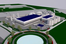
I still have one channel ready getting dust in my shack. To much projects to less time, maybe this winter after building my biogas plant i have more time.
I still have one channel ready getting dust in my shack. To much projects to less time, maybe this winter after building my biogas plant i have more time.
Attachments

- Home
- Amplifiers
- Tubes / Valves
- GU-81m tube amp schematics???