Mark- my roommate who showed me the overhead fence trick actually did the same project of a pyramid. So good! Actually the overhead fence is exactly the same principle, except that the offset piece of MDF is raised to the height of the material. You then apply a jig piece to the top of the piece to be cut with tape loops, which really holds it surprisingly well. Then when you run the piece, the cutoff is not pressing up against the fence, eliminating the chance of kickback. This also lets you use a jig piece on top of a slightly larger rough cut piece and use the table saw like a router. This is how I evenly cut all of my horizontal horn supports. Just a slight modification on what you're saying. I'll have to take some pics to better show how small the difference is!
The difference in the plunged angled blade is that you need no follower piece, or template piece. You can slide the piece you want to cut against the fence and you are done if you set it up correctly.
And yes, I agree with you that the vertical cut you made is pretty much the same as the vertical cut I show.
Nice to see someone using their head a bit. Instead of saying it can't be done. Or can only be done nia CNC.
Many exceptionally complicated objects have been made for centuries without the aid of CNC.
Steve- I love taking time to finish projects like that! For me, I am trying to get this done just in time for summer events. I cannot wait to hear ittt!
Mark- my roommate who showed me the overhead fence trick actually did the same project of a pyramid. So good! Actually the overhead fence is exactly the same principle, except that the offset piece of MDF is raised to the height of the material. You then apply a jig piece to the top of the piece to be cut with tape loops, which really holds it surprisingly well. Then when you run the piece, the cutoff is not pressing up against the fence, eliminating the chance of kickback. This also lets you use a jig piece on top of a slightly larger rough cut piece and use the table saw like a router. This is how I evenly cut all of my horizontal horn supports. Just a slight modification on what you're saying. I'll have to take some pics to better show how small the difference is!
xrk- I will try to give the 3D printer a go. If it doesn't work, I'll probably stick to the table saw cutdown with finish sanding on a drill press like Art did.
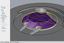
To get the 3D print matching the bass injection ports, my plan is to scan the jig on a scanner (with a ruler placed underneath to get scale set correctly). That should let me perfectly match the profile of the injection ports and also provide the small registration hole present for routing the driver relief channel.
I obviously don't want to print a fully solid part (#1 it would take forever and #2 it would most definitely warp terribly). So I am considering using a 10 or 20 percent fill on the inside to help with both. I do have some ABS, but I have way more PLA. Do you think PLA will suffice? I don't foresee the horn getting hot enough that it would deform. PLA just prints a lot easier on the current setup (no heated print bed and not enclosed). As far as the 10 - 20 percent fill, do you think it would be a good idea to seal the part with something?
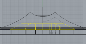
I made a paper template then scanned it to jpg image with ruler tick marks. Then used image as reference for a spline curve. Then create body of revolution with spline. 20% fill is fine with 4 solid layers on surfaces. Drywall screws grab onto 20% infill PLA very well and PL premium adhesive bonds it to wood like no ones business.

Yours looks really good - don't forget to put round radius on edges where ports are to reduce turbulence noise and give room for Xdamage travel to prevent bumping cone into filler plug.
Last edited:
Now.
Are you going to make available your refinements of the drawings?
Absolutely! I built straight from the sketchup CAD document, but was cross checking the plans that Fin made. Everything has been within .2 - .3mm so far.
Once the cone plug is finished I will post the drawing along with the .STL file
Absolutely! I built straight from the sketchup CAD document, but was cross checking the plans that Fin made. Everything has been within .2 - .3mm so far.
Once the cone plug is finished I will post the drawing along with the .STL file
I've been holding off publishing the drawings until they are complete so as not to have any crappy versions out there.
Jenny and I have been tweaking them as we go to make them useful and comprehensive, and I now think they are at a stage ready for comments. Ill find a share to put them on where they can be downloaded and also updated as we go.
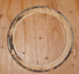
The annotations are those we found useful, including some 1:1 scale printable plans you can lay over the wood to mark!
Jenny's jigs made the cuts very accurate and fast, so I'll tweak the plans to use them in the instructions.
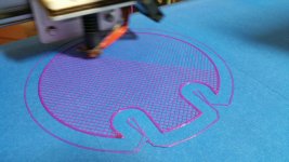
Printing a test piece!
xrk- which edges need to be rounded?
The sharp edges where the port holes go through the volume plug. All the air in the cone has to flow past that sharp 90 deg bend on its way to the horn.
Look at mine:
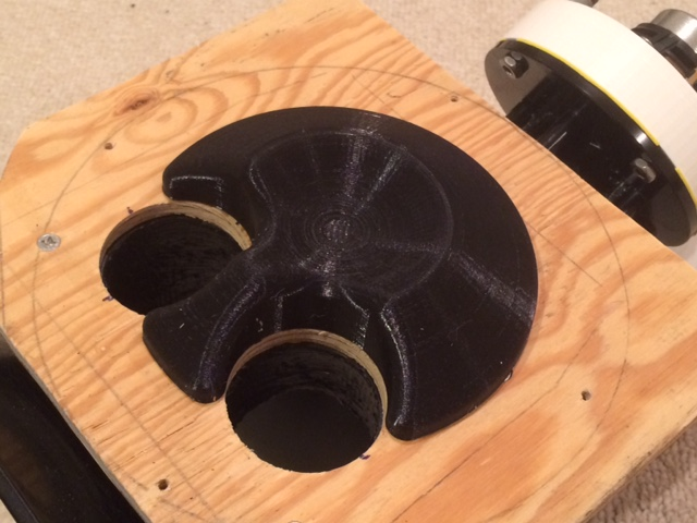
Is there any difference between having the plug closer to the edge of the cone vs the dustcap? Both are 12mm from x-null at the closest.
Reason I ask is because I am getting better prints (less warping at the base) with the one on the right.
Danke schön!
Reason I ask is because I am getting better prints (less warping at the base) with the one on the right.
Danke schön!
Attachments
Or maybe it is best to keep the profile as far away from the cone as possible, and just reduce overall height?
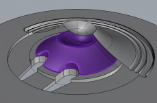
Something like this
P.S. xrk- how do you recommend mounting it? I am thinking about installing another tee-nut for a bolt-through mount, with a bead of silicone adhesive around (underneath) the edge of the part
Something like this
P.S. xrk- how do you recommend mounting it? I am thinking about installing another tee-nut for a bolt-through mount, with a bead of silicone adhesive around (underneath) the edge of the part
Attachments
I would not use silicone because of the out gassing is a bit corrosive.
For testing I would use a double sided mounting tape and when you are ready for final installation I would recommend you fully bond the plug to the surface to avoid issues with rattling or resonance. I would also wipe down the plastic with acetone to chemically fuse it together so it hopefully will never split or crack.
For testing I would use a double sided mounting tape and when you are ready for final installation I would recommend you fully bond the plug to the surface to avoid issues with rattling or resonance. I would also wipe down the plastic with acetone to chemically fuse it together so it hopefully will never split or crack.
Thanks Dan!
Do you think PLA plastic is a bad idea? My printer is not set up for ABS at the moment.. No heated build platform and not enclosed- so far been printing with PLA, meaning acetone vapor bath is not an option.
I suppose I could mount the heat gun underneath the bed for the time being 😉
Do you think PLA plastic is a bad idea? My printer is not set up for ABS at the moment.. No heated build platform and not enclosed- so far been printing with PLA, meaning acetone vapor bath is not an option.
I suppose I could mount the heat gun underneath the bed for the time being 😉
The idea is to reduce the volume between the filler profile and the cone as much as possible while still allowing for 12mm (one way) Xlim travel.Or maybe it is best to keep the profile as far away from the cone as possible, and just reduce overall height?
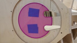
I routed the exterior channel to 5mm, the interior channel to 6mm, as the inner roll of the surround protrudes more than the cone or outer surround rolls when reaching Xlim.
Another shot can be seen in post #138.
Your filler profile conforms more closely to the dustcap, so should end up being about the same volume reduction as the original flat top plywood discs.
Art
Attachments
Last edited:
I'm no expert as I don't personally own a machine. If you can run parts on your machine that can can handle light abuse without delaminating you should be good to go.
Wow, what an incredible job by all…
Art for coming up with the concept and taking it to fruition to prove the concept
Fin for making CAD drawings to allow for more detailed part drawings
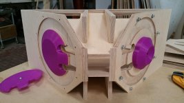
Jenny for showing how well it can be made when you have tools and cabinet making knowledge
And everyone else who provided inputs and encouragement along the way
I have an idea for a jig to make the phase plug using a router.
I’d like to draw it up to scale but have a few questions that some of you can answer off the top of your head and will save me lots of time searching the posts.
What is the major diameter, minor diameter and thickness of the phase plug?
Also, I’m assuming that the plug can have a flat top?
Bob
Art for coming up with the concept and taking it to fruition to prove the concept
Fin for making CAD drawings to allow for more detailed part drawings
Jenny for showing how well it can be made when you have tools and cabinet making knowledge
And everyone else who provided inputs and encouragement along the way
I have an idea for a jig to make the phase plug using a router.
I’d like to draw it up to scale but have a few questions that some of you can answer off the top of your head and will save me lots of time searching the posts.
What is the major diameter, minor diameter and thickness of the phase plug?
Also, I’m assuming that the plug can have a flat top?
Bob
Slight OT:
Autodesk Fusion 360 has an entitlement that is open to everyone:
"Access the same design software used by industry leaders worldwide. A free 3-year license is available for students, teachers, and academic institutions.
A free 1-year startup license is also available for hobbyists, enthusiasts, makers, and emerging businesses that make less than US$100,000 in revenue per year. At the end of 1 year, you can reselect the startup entitlement or transition to a commercial entitlement."
3D CAD/CAM Software for Product Design | Fusion 360
Bob. Thanks for your input. I think I may see what you are onto... Layers of ply at different circle cut radii?
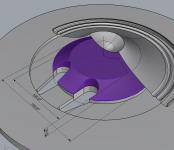
Here are the dimensions, looking forward to seeing what you're up to 🙂
Here are the dimensions, looking forward to seeing what you're up to 🙂
Thanks for the info, Art! So it sounds like the shape doesn't matter as long as the phase plug cannot contact the cone under xlim and doesn't obstruct the injection ports.The idea is to reduce the volume between the filler profile and the cone as much as possible while still allowing for 12mm (one way) Xlim travel.
I routed the exterior channel to 5mm, the interior channel to 6mm, as the inner roll of the surround protrudes more than the cone or outer surround rolls when reaching Xlim.
Another shot can be seen in post #138.
Your filler profile conforms more closely to the dustcap, so should end up being about the same volume reduction as the original flat top plywood discs.
Art
Attachments
Is there any difference between having the plug closer to the edge of the cone vs the dustcap? Both are 12mm from x-null at the closest.
Reason I ask is because I am getting better prints (less warping at the base) with the one on the right.
Danke schön!
That's a great photo. Volume is volume so doesn't matter as long as takes up volume. Make sure it's not porous - infill needs a solid exterior wall/shell or leaks won't take up the volume you want reduced.
- Home
- Loudspeakers
- Multi-Way
- SynTripP: 2-way 2-part Virtual Single Point Source Horn