My expectations where that a number of BPPBP users would have opted for a state of the art remote control.
So far only one member has asked for the Gerbers of the relay board.
For me it was just fun to do the design, I have no personal financial interest, but I´m just a bit surprised.
A preamp without remote control is only half a preamp.
Hans
So far only one member has asked for the Gerbers of the relay board.
For me it was just fun to do the design, I have no personal financial interest, but I´m just a bit surprised.
A preamp without remote control is only half a preamp.
Hans
Correction: A preamp without remote control is no preamp 🙂
I noticed that almost all songs that I play (via Daphile --> ODAC --> Rotel --> Troels Gravesen Ellam 98 Mk II) need volume adjustment. It is a pain to get up so many times!
I noticed that almost all songs that I play (via Daphile --> ODAC --> Rotel --> Troels Gravesen Ellam 98 Mk II) need volume adjustment. It is a pain to get up so many times!
Hans: I must apologise as I should have asked, but Backlog of stuff has grown out of control. I blame the man-cub. Due to this not yet worked out where the main adjustment point will even be in my system. But I will need 6 channels initially going to 8 in the future, so controlling it within my budget will be the issue. But I have not forgotten and will be in touch sometime!
Hans, your design looks very nice and there is a good chance me and perhaps many more will come to seek you soon. Many of the group buy delieveries are still in shipping and few have got them yet and even fewer got it running probably. So it'll need people to first get the taste of it and then the upgrade bug will bite soon 😉
Hans, your design looks very nice and there is a good chance me and perhaps many more will come to seek you soon. Many of the group buy delieveries are still in shipping and few have got them yet and even fewer got it running probably. So it'll need people to first get the taste of it and then the upgrade bug will bite soon 😉
O.K. Fair enough. Take one step at the time.
Hans
My expectations where that a number of BPPBP users would have opted for a state of the art remote control.
So far only one member has asked for the Gerbers of the relay board.
For me it was just fun to do the design, I have no personal financial interest, but I´m just a bit surprised.
A preamp without remote control is only half a preamp.
Hans
For me, it imposes too much on the design of the pre-amp casing, e.g the depth of the front panel (I guess it could be set back in a thick front facia with a perspex, tinted window) and the graphics/type of display used will also begin to dictate on the design..
Think I'm going to eventually go for discrete indications of input and volume, small LEDs and either numerical or positional indicator (turning knob basically).
Then again, I've only ever had one preamp with a remote in my hifi lifetime..
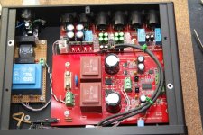
The HPR and HNR regulators only fit the PCB, if the black face is towards the adjacent smoothing capacitors.
There is no labelling on the regs.
Is this the correct orientation for the Putzeys' regulators?
There is no labelling on the regs.
Is this the correct orientation for the Putzeys' regulators?
The HPR and HNR regulators only fit the PCB, if the black face is towards the adjacent smoothing capacitors.
There is no labelling on the regs.
Is this the correct orientation for the Putzeys' regulators?
Yes, it is.
Regards,
Braca
Attachments
The HPR and HNR regulators only fit the PCB, if the black face is towards the adjacent smoothing capacitors.
There is no labelling on the regs.
Is this the correct orientation for the Putzeys' regulators?
This is how they should be mounted

Hans
P.S. Braca was just replying to the same question, now you have double proof.
Last edited:
This is the B.Putzeys reply on what effect the track resistance non-linearlity has. And he follows up with the comment that the distortion plot (in both the Linear Audio and the EDN articles) is for the log law vol pot, instead of for a linear vol pot that he should have fitted. To date I have not seen the linear law distortion plots. Has he published them?
Darren McDougall
What is the non-linearity dependent on pot-track current-density? Does the track resistance get modulated by the audio-signal?
Jul 5, 2014 8:50 AM EDT
Reply
brunoputzeys
It does. Carbon ink is notably nonlinear for instance. Other types may be better. At low frequencies the temperature dependence of the resistive material becomes noticeable. This circuit arrangement helps minimize the impact on distortion of these problems.
After publishing the graphs I found that I'd inadvertently stuffed a logarithmic pot on the board (quite something after all that pontificating about it needing to be linear). Indeed, after I'd fixed that the distortion at LF went away too. Score for theory. I might put up the new measurement one day. It looks a sight better than the one in the article.
The funny thing about ohm's law is that there are no resistors that follow it exactly. Every resistor data sheet gives an indication of the extent in which it deviates. If this info is not stated it just means that it's missing 🙂
Jul 7, 2014 9:35 AM EDT
Yes, it is.
Regards,
Braca
My LEDs light up just like in post408.This is how they should be mounted
View attachment 545056
Hans
P.S. Braca was just replying to the same question, now you have double proof.
Thanks gents.
I measured a voltage offset at the XLR inputs. That offset swaps when the input relays are activated.
I have not tried adding an actual XLR cable with a true source resistance attached.
Is the offset at the inputs normal?
Will it disappear when an active source is connected?
If the source is not active, will the offset return?
Last edited:
Did some finger type temperature checks.
At 15Vdc at the input to the regulators, they run warm.
At 17Vdc at the input to the regulators, they run hot to my finger.
At 14Vdc the output of the regulators is still pretty close to set points.
At 13.5Vdc the outputs have dropped below set points.
Looks like the regulators need something of the order of ±14Vdc to ±17Vdc at their input pins. Accounting for the voltage drops across the two sets of 2r2 melf resistors it looks like a 12-0-12Vac transformer is about right.
The adjacent smoothing caps will receive radiated heat from the regulators and will not like high supply voltages.
I wonder whether I need to consider adding a couple of layers of shiny aluminium cooking foil between the reg black coating and my 105°C capacitors?
Last edited:
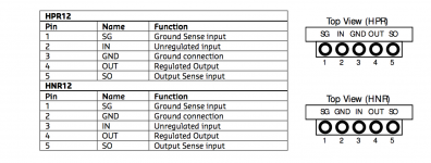
Do the layout do anything with the sense lines or is it just a 3 term regulator at the place they are sitting?
//
//
The B.Putzeys' regulators fit the 5pin locations for the B.Putzeys' bal vol pot.
But the PCB has been designed to take 3pin 7812 & 7912 regulators. located in the middle three pins. The PCB is silk screened to show what orientation the lm7812/7912 are placed.
It's the 5pin without a heatsink face that are confusing, to me.
But the PCB has been designed to take 3pin 7812 & 7912 regulators. located in the middle three pins. The PCB is silk screened to show what orientation the lm7812/7912 are placed.
It's the 5pin without a heatsink face that are confusing, to me.
Did some finger type temperature checks.
At 15Vdc at the input to the regulators, they run warm.
At 17Vdc at the input to the regulators, they run hot to my finger.
At 14Vdc the output of the regulators is still pretty close to set points.
At 13.5Vdc the outputs have dropped below set points.
Looks like the regulators need something of the order of ±14Vdc to ±17Vdc at their input pins. Accounting for the voltage drops across the two sets of 2r2 melf resistors it looks like a 12-0-12Vac transformer is about right.
The adjacent smoothing caps will receive radiated heat from the regulators and will not like high supply voltages.
I wonder whether I need to consider adding a couple of layers of shiny aluminium cooking foil between the reg black coating and my 105°C capacitors?
I bent my regs backwards about 45 degrees to lower radiation to the rest of the board.
Note that you need to do this (if you want to) BEFORE soldering them!
Jan
Where did you find that table?You have this right?
It's not in the EDN series of articles.
Time and again, I am asked on my email address to explain how a Linear pot can be non-linear, and why adding a resistor is bad news.
That's why I have posted it now in this thread. Hopes it helps to understand the underlying cause.
Let me try to explain it in a more mathematical way.
Imagine the track of a pot composed of many pieces, for instance 100, each single piece with the following characteristics: V = A*I + B*I ^2
In case B=0, it would be an ideal resistor with a resistance A and behaviour would be linear, i.e. twice the voltage V gives twice the current I.
In case of B not being zero, the relation voltage to current is no longer linear , although the pot is linear (f.i. the taper in the middle position divides de pot in 2 equal parts).
Let’s take A = 1 and B = 0.01, and I1 = 1 Amp and I2 = 2 Amp, then V1 and V2 are resp.:
V1 = 1*1 + 0.01*1^2 = 1.01 Volt, or R = 1.01/1 = 1.01 Ohm at 1 Amp
V2 = 1*2 + 0.01*2^2 = 2.04 Volt, or R = 2.04/2 = 1.02 Ohm at 2 Amp
This clearly shows the non-linearity of this resistance, which behaviour simply results in distortion.
Now let's set the taper in position Y, with Y lying between 0 and 100, giving the two parts the ratio (Y) / (100-Y)
If no current flows in or out from the taper, which is definitely the case with the feedback setup as used in the BPPBP, current I in both legs of the pot will always be the same, so all 100 individual elements will also carry the same voltage V.
Gain will now be:
[Y*(A*I + B*I^2)] / [(100-Y)*(A*I + B*I^2)] = [Y] / [100-Y]
So out of the magic, the whole non linearity of the individual elements has been cancelled by using this feedback topology, no matter how non-linear the track law is.
Only the ratio of the pot setting determines the gain, but also note that Y may never be 100 !!
Now see what happens when adding a resistor R in one leg of the pot.
[Y*(A*I + B*I^2)] / [(100-Y)*(A*I + B*I^2)]+I*R =([Y] / [100-Y]) * (A*I + B*I^2) / ({A+R}*I +B*I^2)
Without going into further details, it is obvious that the elegant elimination of non-linearity is no longer available.
But, what you could do is to add a SECOND pot, exactly the same as the volume pot, thus having the same non linearity.
In that way, you can use the first pot for volume setting and the second pot as a variable resistor Z.
The algorithm would then become:
[Y*(A*I + B*I^2)] / [(100-Y)*(A*I + B*I^2)]+Z*(A*I + B*I^2) =([Y] / [100-Y+Z]) * (A*I + B*I^2) / (A *I +B*I^2) = [Y] / [100-Y+Z]
And again, the non-linearity has now been completely removed, and also [100-Y+Z] can never become zero, preventing a gain of infinity.
Hopes this explanation helps to get this problem out of the way forever.
Hans
Where did you find that table?
It's not in the EDN series of articles.
Just as a warning and only as a possible bug fix to you all using the Hypex Regulators.
Probably depending on the make of the electrolytic capacitors, some oscillation on the supply voltage may occur, in my case close at 40Khz.
By short circuiting the output sense line to the output line of the Hypex module on the PCB directly at where the module is placed, this problem was fully cured.
It is also possible to make this short circuit directly on the Hypex module itself.
Hans
P.S. Andrew, table to be found on the Hypex site
Where did you find that table?
It's not in the EDN series of articles.
"Datasheet" further down the page...
https://www.hypexshop.com/DetailServlet?detailID=2014
//
- Home
- Source & Line
- Analog Line Level
- BPPBP - Bruno Putzey's Purist Balanced Preamp (well a balanced volume control really)