Just read the very long review of the F7 at 6moons. They really took it seriously. I recognized the described shortcomings of the F5, a bit sharp and lack a little bass. I am excited that to hear that the F7 addresses these small "issues". Right now I am using my DIY F5 only for low midbass and use a cheap tube amp from 500Hz upwards. I tried vice versa but I can't relax without the tube amp for upper mids and highs. My DIY F5 is just too clear for the tweeter. I will sit here and stare at wall flowers until Nelson Pass sell his 100th F7.
Last edited:
I missed this and it was right in my face.
One more question, though.
Does anyone know whether F7 schematics will be shared with the DIY community eventually or not? ...given the fact Firstwatt is part of PassLab now.
Does anyone know whether F7 schematics will be shared with the DIY community eventually or not? ...given the fact Firstwatt is part of PassLab now.
After enough of them have been sold. The number use to be 100 but with the popularity of Firstwatt products the number probably has been increased to when sales fall off significantly enough. Nelson is most kind and generous doing this where most companies would not even think of doing such.
Nelson is most kind and generous doing this where most companies would not even think of doing such.
I am quite new to the DIY world and only recently discovered all the things Mr. Pass shared with the community. I must admit I admire his way of contributing to the world, quite remarkable.
Plenty of fruit hanging off the tree around here no need to wait you could build your own F7. If you are not ready for that mind bending work, the Sony Part 2 is soon to be released, and circuits like F6, M2, Aleph J, F5, F4 and many others are already available.One more question, though.
Does anyone know whether F7 schematics will be shared with the DIY community eventually or not? ...given the fact Firstwatt is part of PassLab now.
the Sony Part 2 is soon to be released.
What does this mean?
This means, there will be a kit consisting of pcb, brackets and 2 pairs of 2sj28/2sk82 available in the diyaudio store:
http://www.diyaudio.com/forums/pass-labs/276711-sony-vfet-amplifier-part-2-a.html#post4397361
http://www.diyaudio.com/forums/pass-labs/276711-sony-vfet-amplifier-part-2-a.html#post4397361
Last edited:
By the time the F7 schematic is officially released, there will be new toys to
distract them.
😎
distract them.
😎
By the F7 circuit is available they'll be begging for the F8...then the F9...and so on and so on. Like a bunch of junkies. 
Graal is , same as Buddha , everywhere ;
already .
enjoy in this valley , same as in previous and next hill
already .
enjoy in this valley , same as in previous and next hill
Is schade feedback considered current feedback ? If so could Nelson have applied some schade feedback around the input jfets ?
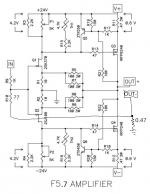
I think I may try modifying my F5 to incorporate PCF, just to see what the fuss is about... It seems that I can just pry up the grounded end of R10, return the negative speaker terminal to ground through a 0.47-ohm resistor and connect the freed end of R10 to the junction of the speaker minus and 0.47-ohm resistor. This is shown in the attached schematic. But, what is an appropriate value of R10 (currently 100k in my amp) with this mod? I am afraid the formulas posted earlier by lhquam are of little help since I don't know the CLG or gm of the amp. Do I also need to change the value of R9?
Attachments
In the case of the F5 with IRFP devices the damping factor is already quite respectable, you possibly might not notice a large difference.
Probably still worth the effort just for the fun of it though, so go for it.
Probably still worth the effort just for the fun of it though, so go for it.
Is schade feedback considered current feedback ? If so could Nelson have applied some schade feedback around the input jfets ?
Generally speaking no, and I did not use Schade feedback on this piece.
There is some unnecessary confusion about current feedback, as a whole
category of amplifiers have come to be named as current feedback amplifiers
(CFA) when in fact they are not sensing current through the load, but simply
employing low impedance negative voltage feedback.
So amusingly, the F7 does that also, so it could be described as a current
negative feedback amp also having positive current feedback.
In this case, the positive current feedback is from sensing the actual load
current.
😎
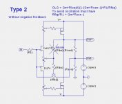
Hello lhquam. I hope that you are well. Your topologies for a diy-like F7 use both overall negative feedback [ONF], and positive current feedback [PCF] in certain proportions. Granted that you've assembled; say a Type 2. Will it be practical, and valuable to operate your prototype with only its prescribed PCF, and without ONF?
Hello lhquam. I hope that you are well. Your topologies for a diy-like F7 use both overall negative feedback [ONF], and positive current feedback [PCF] in certain proportions. Granted that you've assembled; say a Type 2. Will it be practical, and valuable to operate your prototype with only its prescribed PCF, and without ONF?
I assume that your are using the term "positive current feedback" to mean "positive feedback" of the sensed "output current".
The circuit topologies I presented earlier in this thread provide equations for the feedback resistors which create (theoretically) zero output impedance. If the negative feedback resistance is forced to infinite (i.e. is removed), the equations cannot be satisfied and the circuit WILL not performs as desired.
You question is whether one could create a useful amplifier with only positive feedback. The following is the Type-2 configuration without the negative feedback resistor. With suitable choice of the positive feedback resistor with will work and not oscillate. But the without negative feedback the output voltage is linearly dependent on the impedance of the (speaker) load. The only reason I can see for using positive feedback in this manner is to increase to Gm of the circuit.
Attachments
- Home
- Amplifiers
- Pass Labs
- First Watt F7 review