I really don't want to get into this further as it's a side and somewhat off the topic of this thread. If your happy that's good enough.
I think everyone would be more than happy with the in-room FR below.
Attachments
This is the statement I am uncomfortable with:
'Now I want to make a statement that I believe is an essential issue. The voltage source can produce current - no doubt about that - the problem is that it can also produce current of any phase angle. But a genuine current source can only produce a phase angle of zero since it sees it own output impedance as a series resistor of (ideally) infinite value. The voltage produced across the final load will always track current and voltage together without contamination.'
Jan
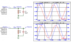
OK, went and simulated such a situation. A voltage source driving a reactive network, versus a current source driving the same reactive network.
Graphs show voltage across the network (left axis) and current through the network (right axis).
Top with a 1V, 1kHz V-source. As predicted by theory, the current leads the voltage because of the C.
Now I changed the V-source to an I source, with the same amplitude as the current that I saw in the voltage drive case, which happened to be 161mA.
The result - exactly the same! This current generates the same 1V amplitude across the network as in the first case. Phase shifts are the same in magnitude and relation.
Only difference is the start of the zero crossing of the generator, which is (of course) voltage in the 1st case and current in the 2nd case.
So you may want to remove this 'essential statement' from the project description to avoid further embarrassment.
As well as the 'noise' stuff which also is nonsensical.
Jan
Attachments
Last edited:
Joe may not have wrote what he ment. With a voltage amp, the output voltage "tracks" the input signal(V) and with the current amp it is the output current that "tracks" the input.
Joe may not have wrote what he ment. With a voltage amp, the output voltage "tracks" the input signal(V) and with the current amp it is the output current that "tracks" the input.
Not likely.
He said:
'...[a voltage source] can also produce current of any phase angle. But a genuine current source can only produce a phase angle of zero...'
... which is completely different and shows a basic misunderstanding. At any rate, the statement is completely wrong and should be removed.
Jan
I agree, what he wrote is not correct. But did he mean the current phase angle compared to the amp's input signal?
Last edited:
I agree, what he wrote is not correct. But did he mean the current phase angle compared to the amp's input signal?
Mark, I am having trouble looking into someone's head from about 6000 miles distance.
I only have his writings to go by. He clearly related to the difference in phase behavior of voltage and current sources.
And the statement seems pretty unambiguous, clearly worded and called 'essential'. Not just some arbitrary rambling.
Anyway, I will not continue down this speculation. I noted a statement that I thought was wrong, did some sims to proof it was, and that satisfied me. I am not expecting any thank you for taking the time clearing up a misconception; I know facts and figures are frowned upon by many here.
You or anyone else can of course interpret anything anyway you like for whatever reason you want.
Jan
Mark, it wouldn't make any difference. The simple math (no fancy sim needed) shows that I and V through the load will not be in phase if there's reactance (which every driver has). Period. You can stick an impedance flattening network across the load to waste some power, but I vs V for the load is still unchanged.
Ideas are great, but lots of them are wrong. At some point, an honest practitioner has to say, "Yeah, this isn't right, back to the drawing board." Lord knows I've had to do that quite a few times in my career! 😀
Ideas are great, but lots of them are wrong. At some point, an honest practitioner has to say, "Yeah, this isn't right, back to the drawing board." Lord knows I've had to do that quite a few times in my career! 😀
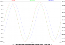
Sy, Here you can see what I mean. The currents though an identical (inductive) load when using a voltage or current amp. The current phase angle is 0 when compared to the input signal.
Yes, but then the voltage phase angle is shifted. I vs V will always have the same phase relationship for a given load, irrespective of the source impedance.
Sy, Jan, that is clear and at the time I was probably just adapting it to make it fit with reality. If the output current "tracks" the amp's input signal, which means that the driver (speaker) also "tracks" the amps input signal independent of the VI phase angle.
If you mean, "the output current tracks the input voltage," yes, of course, that's the trivial definition of a transconductance amp. But that was not what what being claimed.
Try your sim with a pure cap instead of a pure inductor, and you will conclude that voltage drive provides for better 'tracking'.
But your speaker - assembly of xover and drivers - although it contains both inductances and capacitances, is not a pure inductance, nor a pure cap. The phase angles inside that assembly move all over the place with frequency.
This is a dead end street.
Jan
But your speaker - assembly of xover and drivers - although it contains both inductances and capacitances, is not a pure inductance, nor a pure cap. The phase angles inside that assembly move all over the place with frequency.
This is a dead end street.
Jan
Why do we worry about the voltage or its phase angle, even if it moves all over the place with frequency?
All this theory arguments.....FFS.
Guys...... Just try connecting appropriate compensation networks directly across drivers and report back.
The point of this is that circulating currents loop areas are minimised and segregated....this is in essence what Joe is saying.
Network theory/approximation states that there should be no real difference, practise says different.
Dan.
Last edited:
The schematics don't show the networks across the drivers. Look again.
Not even vaguely.
The point of this is that circulating currents loop areas are minimised
Not even vaguely.
I keep saying this, but I think Joe is onto something with the flat impedance idea. Stuff like Common Mode or optimising crossover distortion in Class AB is tremendously difficult, but is the distortion mechanism at work here.
So I think we should consider making speakers an easy load for the amplifier. It seems to work. I do it, especially at the high frequencies where amps run out of open-loop gain. They sound better.
Here's the view of another heretic, Leonard Susskind about string theory:
And this has created a sort of sense of denial about the facts about the theory. The theory is going to win, and physicists who are trying to deny what's going on are going to lose.
See, after a while, Leonard just gets bored with saying the same thing to the doubters.
String theory has anything but won though. LHC has shot quite a few holes in supersymmetry over the last couple of years.
String theory has anything but won though. LHC has shot quite a few holes in supersymmetry over the last couple of years.
Mate we're talking about speakers here. Drowning out good posts with a huge barrage of trivial stuff might win you the forum argument, but the point is that the science wins in the end.
And what amazes me is that none of you really seem to realise that amplifiers are imperfect, compromised and sensitive to load. 😕
Ok, I goofed on what I thought Joe is on about, I just refreshed.The schematics don't show the networks across the drivers. Look again.
Not even vaguely.
So, Joe is saying put conjugate networks across the loudspeaker input terminals.
Agreed this is not optimally minimising circulating currents, and can be majorly improved as per I advocate.
Dan.
Last edited:
- Status
- Not open for further replies.
- Home
- Loudspeakers
- Multi-Way
- Joe Rasmussen Usher S520 "Current Compatible" Crossover