Soren, could you give us an update on the OEM board?
After getting the dac1101 out, the dam1121 is next, I have production hardware, but still some work and docs to do, things always take more time than expected.... Please don't bug me, when it's ready I'll announce it.
Don't worry, be happy! You've got an answer!Soren, could you give us an update on the OEM board?

Maybe I need counseling on the tone of my messages. Not sure how that question could have been understood as bugging or worrying
Maybe I need counseling on the tone of my messages. Not sure how that question could have been understood as bugging or worrying
Sorry, not personal, you just happened to be the 50th (or something) that asked about the dam1121.....
Wow! Thanks everybody. I am in for two DAM1121 when they are available. Big thanks to Soren for offering them to DIYers!
Where I’d like to get confirmation or opinions are the following:
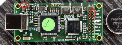
When I use external 3.3V for Amanero I only have to cut 1 trace as described at post #878. How to connect external 3.3V to Amanero board? To C27 as the post #878’ picture says or I can use GND and 3.3V output of the Amanero’s output connectors, does it matter?
According to Domenico of Amanero just remove the resistor at L1 and connect external power to GND and 3.3V output of the Amanero board. I did that and it works.
Attachments
Of course, that's why the incoming jitter doesn't matter, assuming no bit errors, as it's reclocked and buffered so the dam1021 clock circuit define the jitter. But the clock oscillator and FPGA have low jitter, not as low as what's possible, but low enough that the dam1021 sounds pretty damn good.... Has actually been discussed early on in this thread.
If you look very close on the dac1101 and dam1121 pictures you might notice some small flip flops between the fpga and the shift registers 🙂
So soren how much jitter is reduced because of the post flip flop circuit after FPGA is observed?
Sounds like...
Soren needs some time for work, hahaha. And I am not sure he has the appropriate resources for actually measuring this. My understanding is that clocking in an FPGA is limited, likely because of the noisy environment. By re-aligning the data directly with the masterclock via flip flop right before conversion, the jitter level should end up right at the level of the clock accuracy, plus a little more for losses due to pcbs trace, etc...
So soren how much jitter is reduced because of the post flip flop circuit after FPGA is observed?
Soren needs some time for work, hahaha. And I am not sure he has the appropriate resources for actually measuring this. My understanding is that clocking in an FPGA is limited, likely because of the noisy environment. By re-aligning the data directly with the masterclock via flip flop right before conversion, the jitter level should end up right at the level of the clock accuracy, plus a little more for losses due to pcbs trace, etc...
I'm not really convinced the jitter on a dam1021 is noticeable, but then again I come from old DS dac's with crappy clocks where its a night and day difference.... Kudos to Soren for improving the design to keep certain types pleased however....
Digital Volume Control
The digital volume control being able to give us +10dB gain is something I am still unhappy with, I would rather have it stop at 0DB.
One example why is a review about the dac1101 I read there:
Soekris R2R DAC/Amp | Page 3 | Super Best Audio Friends
The reviewer complains about the 1101 compressing a bit and sounding slightly strained, compared to his tube dac.
And that after he adjusted volume by ear just going back little bit from full gain on the 1101.
What is a little bit? -5dB? -3dB? But than he is clipping transients on digital full scale mastered material (which is more or less all pop music from the last 15 years)
Clipping a few dB sounds not like hard distortion but more like he described the sound signature of the 1101.
On a commercial product without an exact visual representation of the digital gain (via digits) I would stop at 0dB full scale.
the problem is people will review it at 10db
though im not sure why you'ld compare it to something with a valve output stage
though im not sure why you'ld compare it to something with a valve output stage
Then read the instruction manual, 10 "clicks" down is 0 dB, works great in 1 dB steps.
I cannot find that in the manual, but no matter how exactly you can set it, any (consumer) digital audio device should scream ATTENTION if the volume exceeds 0dB full scale...
That's right, make sense more than 0dB not have been annoyed me about it.
Page 4 under the table ...
Page 4 under the table ...
I suppose that if one can attenuate without loss we can also amplify... as long as the signal don't clip it should be OK. But when it do its over.
I play my DAM with a filter with 6dB attenuation - sound always clean. I wonder how the new products behave wrt. this?
//
I play my DAM with a filter with 6dB attenuation - sound always clean. I wonder how the new products behave wrt. this?
//
I suppose that if one can attenuate without loss we can also amplify... as long as the signal don't clip it should be OK. But when it do its over.
I play my DAM with a filter with 6dB attenuation - sound always clean. I wonder how the new products behave wrt. this?
//
Filter 6dB? Do you do that in the converter, or before? I have the DAC to 0db, reckon the MAC 6 dB down and have the best result. No real idea why that works better, but it does it?!?
Yes the attenuation was incorporated in a filter from the "more dam filters" site.
Oops sorry it was -3,5dB
http://www.moredamfilters.info/content/eqhq-variations-v1
//
Oops sorry it was -3,5dB
http://www.moredamfilters.info/content/eqhq-variations-v1
//
It should be doable (in firmware) that the FPGA reports clipping.
I think that would be a nice feature. The easiest is to report via serial interface. Some statistics (how many clips...) would also be nice. And perhaps even this could be put out at some unused pin for a LED indicate clipping.
I think that would be a nice feature. The easiest is to report via serial interface. Some statistics (how many clips...) would also be nice. And perhaps even this could be put out at some unused pin for a LED indicate clipping.
- Home
- Vendor's Bazaar
- Reference DAC Module - Discrete R-2R Sign Magnitude 24 bit 384 KHz