1W 12V zener diodes is all that need to be changed so it will output 12V instead of 18V.
Load with 3 op-amps or without load BD will have same themperature.
Regards
I like this shunt regulator design. What is the output voltage ripple level with this design? Very simple will have to try it.
Thanks for a neat preamp power supply.
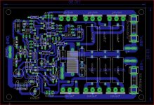
hello guys I want to share this layout it has two versions 4P and 2P feel free do modified if you want 🙂 I have the idea of also make it with MT-200 power transistors but I didn't complete but is on the same file 🙂
if you don't have 7zip here is the link is free of course
7-Zip
if you don't have 7zip here is the link is free of course
7-Zip
Attachments
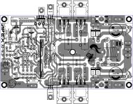

hello guys I want to share this layout it has two versions 4P and 2P feel free do modified if you want 🙂 I have the idea of also make it with MT-200 power transistors but I didn't complete but is on the same file 🙂
if you don't have 7zip here is the link is free of course
7-Zip
Thanks friend for sharing
this is not new I already did it in 2014 but since YouTube flag for using copyright music I find out that you can use free music from YouTube I have to re-adjusted to about 20mV and sounds pretty good sorry I made the video in Spanish but a place some captions 🙂
https://youtu.be/WX2GY27jYn0
https://youtu.be/WX2GY27jYn0
FX8 Boards Arrived
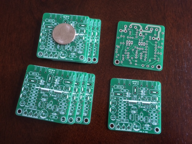
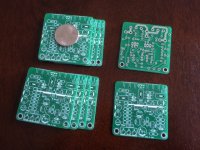
It took a while but the micro 50mm x 50mm FX8 boards arrived. It is tiny!
Thanks to Apex and all the folks who designed and tweaked the PCB. I am still waiting for the BOM to arrive from the slow boat from China.
Looking forward to this build though. Looks like it will go fast given the simplicity of the design and small form factor.
Attachments
It took a while but the micro 50mm x 50mm FX8 boards arrived. It is tiny!
Thanks to Apex and all the folks who designed and tweaked the PCB. I am still waiting for the BOM to arrive from the slow boat from China.
Looking forward to this build though. Looks like it will go fast given the simplicity of the design and small form factor.
Nice
It took a while but the micro 50mm x 50mm FX8 boards arrived. It is tiny!
Thanks to Apex and all the folks who designed and tweaked the PCB. I am still waiting for the BOM to arrive from the slow boat from China.
Looking forward to this build though. Looks like it will go fast given the simplicity of the design and small form factor.
thats compact!. smaller than most chip amp pcbs😀
Last edited:
Hi, I found interesting page for replacement transistor
Small Signal Transistors | VAS Transistors | Driver Transistors | Output Transistors
Maybe someone come in handy.
Output Transistors
Small Signal Transistors | VAS Transistors | Driver Transistors | Output Transistors
Maybe someone come in handy.
Output Transistors
Hi, I found interesting page for replacement transistor
Small Signal Transistors | VAS Transistors | Driver Transistors | Output Transistors
Maybe someone come in handy.
Output Transistors
Thanks - that is indeed useful. I am looking for substitutes right now. Thanks!
Apex i can put darlington to AX14 ?
I have 5 pairs 2SB1559/2SD2389 and lair about year...
My AX14 has burned out (DC) and MDS08 too 🙁
And I wonder if I can use darlington?
I dont have bass now
Replace 2SC4793 to 2SD2389 and 2SA1837 to 2SB1559
Remove r20 r21 r22, and jumper emitter to 0.33R
What do you thing ?
DC in OUT:
I have 5 pairs 2SB1559/2SD2389 and lair about year...
My AX14 has burned out (DC) and MDS08 too 🙁
And I wonder if I can use darlington?
I dont have bass now
Replace 2SC4793 to 2SD2389 and 2SA1837 to 2SB1559
Remove r20 r21 r22, and jumper emitter to 0.33R
What do you thing ?
DC in OUT:
Attachments
Last edited:
Hi,
Many many happy returns of the day Mr.Mile,Hope you have a great day !
I have been using this for some time,Absolutely useful !
Transistor BC550 - BC551 - BC556 - specification
Regards.
Many many happy returns of the day Mr.Mile,Hope you have a great day !
I have been using this for some time,Absolutely useful !
Transistor BC550 - BC551 - BC556 - specification
Regards.
What about fuses and DC protect?Apex i can put darlington to AX14 ?
I have 5 pairs 2SB1559/2SD2389 and lair about year...
My AX14 has burned out (DC) and MDS08 too 🙁
And I wonder if I can use darlington?
I dont have bass now
Replace 2SC4793 to 2SD2389 and 2SA1837 to 2SB1559
Remove r20 r21 r22, and jumper emitter to 0.33R
What do you thing ?
DC in OUT:
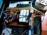
One fuses burn, resistor 220R, and 2sc/sa.. and don't have DC protect yet.
Maybe too much voltage +/-60V DC
Work good long time with XL2
Now i know why DC protect is needed ... i always put off later.
Apex and so about darlington?
I can use this pair ?? For D14@A100 ??
Maybe too much voltage +/-60V DC
Work good long time with XL2
Now i know why DC protect is needed ... i always put off later.
Apex and so about darlington?
I can use this pair ?? For D14@A100 ??
One fuses burn, resistor 220R, and 2sc/sa.. and don't have DC protect yet.
Maybe too much voltage +/-60V DC
Work good long time with XL2
Now i know why DC protect is needed ... i always put off later.
Apex and so about darlington?
I can use this pair ?? For D14@A100 ??
Yes you can use it for D14 and I suggest FX100 PSU with DC and short protect.
And yes +/-60V DC is to much voltage
Last edited:
Would FX8 work with swapped in BJT's?
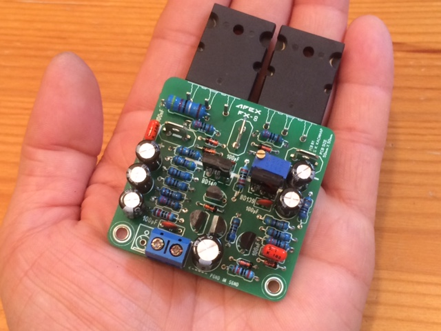
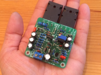
This amp is super easy to build - went together faster than any amp I have built. I am still waiting for the output stages but have some 2SC5200/2SCA1943's slipped in their place to get a feel how big this amp is. It is small! Smaller than a typical TPA311x class D amp.
I am a bit impatient waiting for the MOSFETs to get here...
Is there anyway this amp can work with BJT's rather than MOSFETs? What would happen if I powered this up with the PNP on left and NPN on right.
The MOSFETs are G - S - D and the BJTs are B - C - E.
Would it be PNP on left and NPN on right given Vcc(+) is on left and negative is on right side.
Attachments
Last edited:
- Home
- Amplifiers
- Solid State
- 100W Ultimate Fidelity Amplifier