Hi Guys
Another reason to always drive mosfet gates from a low-z is to eliminate modulation of the channel resistance caused by the channel current. Even in a power supply where the mosfet is just a voltage follower, too high a gate impedance will cause audible impairment to the sound.
For example, a tube amp with a mosfet voltage regulator had a completely different sound with low-z and high-z gate drive. This was a dynamic condition and surprising to hear. It should be more imortant with the mosfet in the signal path, so any mosfet amps I've built always have a drive stage.
And now, my DS impression: I have a theory as to why this happens, but this is not the place to disclose it...
Have fun
Hi Albert,
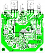
The things I had to change on your layout were adding a ground wire for the 100uF cap lower right. Add 10pF cap at the feedback resistor. Your VBE trimmer is wired incorrectly. cut the trace and connect the other side. Invert the LED at the VBE. I had to use a 500R trimmer to get the correct bias. Total, including the 510 resistor is around 740ohm so if you want to use the 100R trimmer you may need a 680R resistor in place of the 510. I'm attaching a sprint shot showing the things I had to do. I also needed to lower the 240R resistor to get the offset to zero.
The things I had to change on your layout were adding a ground wire for the 100uF cap lower right. Add 10pF cap at the feedback resistor. Your VBE trimmer is wired incorrectly. cut the trace and connect the other side. Invert the LED at the VBE. I had to use a 500R trimmer to get the correct bias. Total, including the 510 resistor is around 740ohm so if you want to use the 100R trimmer you may need a 680R resistor in place of the 510. I'm attaching a sprint shot showing the things I had to do. I also needed to lower the 240R resistor to get the offset to zero.
Attachments
Hi Terry,
I have corrected the other errors in my pcb, except the bias trimmer wiper wire connection, I am using a different trimmer model, I will try to correct it this morning.
Have you also used a mains bulb tester in your build?
Cheers!
Albert
I have corrected the other errors in my pcb, except the bias trimmer wiper wire connection, I am using a different trimmer model, I will try to correct it this morning.
Have you also used a mains bulb tester in your build?
Cheers!
Albert
Yes I use the light bulb tester. I can't even begin to tell you how many parts have been saved.
As for the way you have the VBE wired, if you look at the schematic you will see that you have it wired in series with the 1.8k rather than the 510R.
As for the way you have the VBE wired, if you look at the schematic you will see that you have it wired in series with the 1.8k rather than the 510R.
Hi Terry,
I have corrected the other errors in my pcb, except the bias trimmer wiper wire connection, I am using a different trimmer model, I will try to correct it this morning.
Have you also used a mains bulb tester in your build?
Cheers!
Albert
Hi Albert, you can test much safer, if you remove the output transistors, temporarily replace R13 (680R) with 2 x 360R in series and connect the middle point to the output (with no load for the time being). You will have much lower chance to damage something.
As soon as you see the circuit works properly - set the trimmer to the minimum bias, put 680R back in place, solder IRFPs back in and finalize the setup, eventualli testing with the load connected.
Hi Guys
Another reason to always drive mosfet gates from a low-z is to eliminate modulation of the channel resistance caused by the channel current. Even in a power supply where the mosfet is just a voltage follower, too high a gate impedance will cause audible impairment to the sound.
For example, a tube amp with a mosfet voltage regulator had a completely different sound with low-z and high-z gate drive. This was a dynamic condition and surprising to hear. It should be more imortant with the mosfet in the signal path, so any mosfet amps I've built always have a drive stage.
And now, my DS impression: I have a theory as to why this happens, but this is not the place to disclose it...
Have fun
Hi Struth, what do you mean by DS?
Hi Guys
Valery: DS = D. Self. He made that statement in a few places in his books. In my books, I either tell you what I know or i don't.
I like your designs! very innovative. I found the current-mode TIS to be very sensitive to device types though and have sim'ed a complementary version that seems a bit less sensitive to that.
Have fun
Hi Guys,
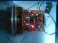
First of all , my apologies for the confusion, while I was reviewing my on board components, I found out that I had actually installed 22r for the mosfet gates, it turns out that the brown color 3rd band was actually black which means 0 or none by color coding. My fault, the correct value is 220r as per with schematic. Upon replacing it with the right value and correcting the bias trimmer wiper connection, the amp awakens!....and after a few adjustment to get the ideal ma/device of the output fets, I introduced some music to it.
I must say sonic wise this compact design is in rank with VSSA and P3A, small circuits with marvelous musical fidelity, VHex is indeed another "less is more" audio technology out there. And yes, Terry is correct in affirming that this amp is dead silent. (fact is my input source cable is 5ft long).
Congratulations Valery!
Just a few confirmation, I got 120mv/device to achieved 80ma/device idle current. Is this normal? You may notice in my build the - rail CCS LED is lit more brightly than the rest. All LEDs are the 5mm type. My installed parts different than the original schematic (the first one, not v1.1)
3.3k for the input supply
47r at the PSU +/- rails
200r for the VBE trimmer (set at 91r) 2N5088 for the input pair.
BDs for drivers only.
DC offset is <1mv (offset trimmer is set at 31r).
Cheers!
Albert
Attachments
Hi Guys
Valery: DS = D. Self. He made that statement in a few places in his books. In my books, I either tell you what I know or i don't.
I like your designs! very innovative. I found the current-mode TIS to be very sensitive to device types though and have sim'ed a complementary version that seems a bit less sensitive to that.
Have fun
Thank you 😉
OK, now I see.
I also played with complementary versions - like them a lot 😎:
- BJT LTPs
- jFET LTPs
Hi Guys,
First of all , my apologies for the confusion, while I was reviewing my on board components, I found out that I had actually installed 22r for the mosfet gates, it turns out that the brown color 3rd band was actually black which means 0 or none by color coding. My fault, the correct value is 220r as per with schematic. Upon replacing it with the right value and correcting the bias trimmer wiper connection, the amp awakens!....and after a few adjustment to get the ideal ma/device of the output fets, I introduced some music to it.
I must say sonic wise this compact design is in rank with VSSA and P3A, small circuits with marvelous musical fidelity, VHex is indeed another "less is more" audio technology out there. And yes, Terry is correct in affirming that this amp is dead silent. (fact is my input source cable is 5ft long).
Congratulations Valery!
Just a few confirmation, I got 120mv/device to achieved 80ma/device idle current. Is this normal? You may notice in my build the - rail CCS LED is lit more brightly than the rest. All LEDs are the 5mm type. My installed parts different than the original schematic (the first one, not v1.1)
3.3k for the input supply
47r at the PSU +/- rails
200r for the VBE trimmer (set at 91r) 2N5088 for the input pair.
BDs for drivers only.
DC offset is <1mv (offset trimmer is set at 31r).
Cheers!
Albert
Hi ALbert,
Great job! Good to hear you like it 😀
Those 120mV - where exactly do you measure?
One LED is brighter than the other one - looks odd as both positive and negative shoulders have got the same current through the LEDs 🙄
Hi Valery,
120mv across each 0.22r that is per device,
I must say this is by far my DIY amp that actually displays accurately equal measurement to both + and - rails, 😎
120mv across each 0.22r that is per device,
I must say this is by far my DIY amp that actually displays accurately equal measurement to both + and - rails, 😎
Hi Valery,
120mv across each 0.22r that is per device,
I must say this is by far my DIY amp that actually displays accurately equal measurement to both + and - rails, 😎
Something is wrong then 🙂
120mV / 0.22R = 545mA
For 80mA you should have 80mA * 0.22R = 17.6mA per each resistor or 35.2mA over both of them.
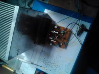
 that is what I'm suspecting..that huge heatsink gets really warm. I actually unsolder a few parts for checking off board and resolder them back. I must've messed up something. I will double check my work in the morning..but it sounds very clean though 🙂
Hi Albert,
What ohm reading do you get from the base of the VBE multiplier to the anode of its diode? I have about 740R. This takes into account the 510R resistor and the trimmer.
What ohm reading do you get from the base of the VBE multiplier to the anode of its diode? I have about 740R. This takes into account the 510R resistor and the trimmer.
Hi Guys,
First of all , my apologies for the confusion, while I was reviewing my on board components, I found out that I had actually installed 22r for the mosfet gates, it turns out that the brown color 3rd band was actually black which means 0 or none by color coding. My fault, the correct value is 220r as per with schematic. Upon replacing it with the right value and correcting the bias trimmer wiper connection, the amp awakens!....and after a few adjustment to get the ideal ma/device of the output fets, I introduced some music to it.
I must say sonic wise this compact design is in rank with VSSA and P3A, small circuits with marvelous musical fidelity, VHex is indeed another "less is more" audio technology out there. And yes, Terry is correct in affirming that this amp is dead silent. (fact is my input source cable is 5ft long).
Congratulations Valery!
Just a few confirmation, I got 120mv/device to achieved 80ma/device idle current. Is this normal? You may notice in my build the - rail CCS LED is lit more brightly than the rest. All LEDs are the 5mm type. My installed parts different than the original schematic (the first one, not v1.1)
3.3k for the input supply
47r at the PSU +/- rails
200r for the VBE trimmer (set at 91r) 2N5088 for the input pair.
BDs for drivers only.
DC offset is <1mv (offset trimmer is set at 31r).
Cheers!
Albert
Hi Albert,
I'm trying to follow what you did. You used 47R rather than 2R in the rails?
You used a pair of 3k3 in place of the pair of 3k6 to load the zeners? I used a single 1k8/1w there.
You may just need to dial the bias way down. I couldn't get below 110mA with the 200R trimmer. Try changing the 510R to 680R and your 200R trimmer will probably be fine.
Hi Terry,
That is correct, I did a quick sim before I made the values changes. I will do an ohm meter reading on the VBE diode later..I also suspect the IRFP odd one to be not functioning in best condition as I needed to bias the amp higher to get a clean music .
That is correct, I did a quick sim before I made the values changes. I will do an ohm meter reading on the VBE diode later..I also suspect the IRFP odd one to be not functioning in best condition as I needed to bias the amp higher to get a clean music .
Hi Albert,
What ohm reading do you get from the base of the VBE multiplier to the anode of its diode? I have about 740R. This takes into account the 510R resistor and the trimmer.
After replacing the 510r with 680r, I got around 711r VBE to trimmer resistance.
That equates to 40mv across both 0.22r or 20mv across each 0.22r. Trimmer resistance is 31r. I have tried using a pair of 3.9k at the CS and it seemed there is not much voltage difference between using 3.3k or a single 1.8k there, I settled for the single 1.8k.
The amp is working great sounds realy good with a fair amount of heat dissipation of the outputs. I do think nothing is wrong with the Fairchild IRFP240 fet. I have tested it in my 6r component speakers, full blast...very good bass drive.
The only thing that puzzles me is the brightly shining LED, measuring across cathode to anode of both +/- CS I got 1.8v and both CS collector trannies have around 4.3v
Sorry late response, very busy weekend.
Hey Albert,
That is great news! That is about 90mA so should be perfect. Maybe one of the LEDs is just brighter than the other. Great job!
That is great news! That is about 90mA so should be perfect. Maybe one of the LEDs is just brighter than the other. Great job!
Hi Terry,
Yes, i do think negative rail LED will shine brightly because Q4 & Q5 does not dissipate current equally. Equal voltage but not on current. Q5 (negative) is about 8ma and Q4 (positive) is at 3.5ma. 😉
Yes, i do think negative rail LED will shine brightly because Q4 & Q5 does not dissipate current equally. Equal voltage but not on current. Q5 (negative) is about 8ma and Q4 (positive) is at 3.5ma. 😉
Last edited:
- Home
- Amplifiers
- Solid State
- IRFP240/9240 Amplifier (simulated on TINA)