Just noticed this while playing with the Inuke dsp.
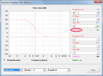
You can boost the signal 15 db with Filter 1 on the parametric eq tab.
You can also boost the signal 12 db with the gain knobs for each channel on the Filter/Crossover tab.
Not sure if the gain stage in the amp that the dsp controls can actually do a clean 27 db dsp boost, but the dsp software suggests it can. if so that's a whole lot of dsp boost.
The graphs only go from 20 hz to 20 khz so it's unclear what the boost would do outside of that bandwidth, but it's probably boosting the entire bandwidth we are interested in (maybe). Might have to measure to make sure the boost extends down to 16 hz.
Maybe someone with an Inuke can try this 27 db dsp boost out and report back on whether it can do it cleanly or not? Also report on whether the lights are reporting input strength, input after volume knobs, input after volume knobs and dsp, or output? There's a bunch of places those lights could be connected to and reporting on. Ideally I'd hope then are reporting signal strength right after the volume knobs and dsp, right before the power amp stage, or even right at the output after the power amp stage (which seems unlikely given the wording in the manual).
Last edited:
LOCAL, LOCAL, "LOCAL media".Why don't you put a request in your local media for somebody who has an oscilloscope to come and help you free. (Give them a charitable donation receipt.) That will immediately reveal signal peaks along the chain and put to rest a lot of questions about power that are not easily answered any other way. A meter or red LED will not tell you much about music signals but a 'scope will do so immediately and tell you much more too.
Ben
Ben
The more I play with the Behringer DSP software the more I like it. Makes me want a big Inuke.
There are petitions for Behringer to offer this DSP as a standalone unit (without an amp) to replace the DCX and DEQ. It's probably already in the works anyway, as the older units are really old and crusty, although still very functional. This Inuke DSP interface is just very nice and user friendly.
There are petitions for Behringer to offer this DSP as a standalone unit (without an amp) to replace the DCX and DEQ. It's probably already in the works anyway, as the older units are really old and crusty, although still very functional. This Inuke DSP interface is just very nice and user friendly.
LOCAL, LOCAL, "LOCAL media".
Ben
Yes, we all saw that.
We also all saw this.
Long ago, I asked if anybody from this forum would have the goodness of heart to visit with you. Zilch. All talk and no.....
Was it the locals in OP's community that you were referring to as being on this forum and being all talk and no action?
Anyway, I think everyone agrees that local help would be very helpful if it's available and free or reasonably priced.
Although the potential for a lot of gain in the digital realm is there, it is best from a signal to noise ratio to do the boosting as near the low-level source as possible, to keep from boosting any induced noise on the line.Another preamp may be required, but that's another component in the chain, another potential for noise, component failure, low frequency roll off, etc.
I'd try to get the most out of what's already there before adding another component, although it may end up being an absolute necessity.
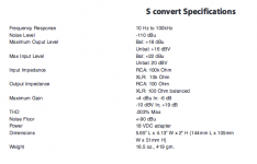
If Bach On locates the Samson "S-convert" near the source and runs balanced XLR cable to the amps, that may be close to enough gain, though many of the midi outputs I have run into have been in the -50 to -30 dBu level, the 19 dB of gain the Samson provides may not be enough for this application.
Art
Attachments
Last edited:
Unfortunately I don't think we can sim shelfs in Hornresp
Attachments
Well look at that, David anticipating my needs before I know my needs.
Seriously though, good stuff. I was aware of the parametric eq wizard but I've never needed to actually use it yet, and was not aware that shelfs could be simulated.
Now the unknown is what the Behringer DSP shelf is doing outside of the 20 hz - 20 khz range. That would have to be measured, I guess.
Good discussions. I'm reading it all and even understanding some of it.
Had choir rehearsal last night. Did some putzing around exploring the electrical stuff. I focused mainly on the electrical circuit.
One piece of bad news is that the two electric radiator heaters in the pipe chamber ARE on the same circuit as the outlet currently driving the amps. I've turned the heaters off for right now, but they will be needed when the weather turns cold again. I checked the upstairs, but not the basement area. The only other item on that same circuit - at least upstairs - is an overhead light fixture in a hallway. (see below). It has something like a 100 watt incandescent bulb. I'll replace it with a low wattage compact fluorescent.
JAG suggested I do a complete census on the panel circuits. That is my plan. It is badly needed. I'm going to get one of the men in my choir to assist. Then I plan to put an updated listing on the panel door. Many of the current item labels on the panel box are so faded you can hardly read them.
Currently (pun unintended), the panel box only has one free blank slot for a 15 amp 120 volt circuit breaker. So adding a lot of extra circuits doesn't look like a likely option. I think it is a 100 AMP panel. It has about 30 circuit breaker slots. Remember the church dates back to 1928 and originally had no electricity.
I experimented a bit with the gain controls on all the amps. Turning up the iNuke does produce more low bass - both at 32 Hz and 16. But at one point it just became too loud when compared to the manual sounds. So I turned it down. I didn't take my laptop computer with the MIDI software, so I couldn't check out the lights on the iNuke.
I had previously mentioned a surface mounted electrical outlet in the nursery near the amp closet. I explored a bit. That outlet is connected to another one in the same room. It is providing power to a window air conditioning unit. So it doesn't look like adding another outlet in the amp closet from that source is a very good plan - especially in the Summer when that AC unit would be used.
I expect the patch cables today. At that point, I can add the Samson bump box to the iNuke input chain. The question is what kind of electrical current is needed for each amp, and for all of them combined. I have a digital Kilowatt meter that measures watts, voltage or amps. I think it has a 3,000 watt maximum measurement capability, though it might be lower. I plan to use it to find out how many watts we will require when the organ is needing the most effort from the amps.
The 220 volt single-phase blower that supplies air for the pipes is in an adjacent closet to the amps. I have a clamp-on meter that can give me some sense of how much current it is using. IT IS POSSIBLE that we could tap into one or more of the legs of that electrical circuit and obtain 120 volts IF we need just a few more watts for one or two amplifiers - but I really don't know right now how many watts the blower is consuming.
My initial thinking is that we MAY have to depend on that single outlet in the amp closet. I could ask the electrician to add a circuit breaker in the electrical panel box to feed the outlet for the heaters in the pipe chamber. That would take them off the load of the amp outlet. I consider the current required for a 22 watt compact fluorescent light an almost insignificant addition to the amp circuit.
I realize that it would be BETTER to have more separate circuits available in the amp closet. But doing so would be difficult - and maybe even impossible
So it looks like I may only have one 15 amp circuit breaker feeding the amps. I yield that this isn't the optimum situation. But the cost of drawing extra power from remote locations may be higher than we (aka: I ) can afford.
I ran across some tests for the Crown XLS1000 amps. They each draw 22 watts at idle. The drain at 4 ohms while running pink noise at 1/3 power with extreme clipping is listed as 118 watts. Running at 1/8 power for pink noise, the current draw is listed as 61 watts. I will measure the figures for OUR amps in our own situation. We will have four of these running at the same time. YES. We can take one or more of them out of service and send more sounds to just one or two pairs of speakers, but I don't want to do that unless I have to.
I've temporarily taken the Crown XLS1500 out of the mix. It is unplugged. BUT I plan to add it back to the mix when I put more bass speakers in the system. But assume for now that it isn't needed.
That leaves the iNuke running at 4 ohms. It will have the Samson bump box inline, so I expect it to draw a larger amount of power than it is using right now. I've read the estimates from Art and others. The Kilowatt meter will probably give me a better sense of the power consumption in our situation using the gain levels I ultimately determine is needed.
Finally, I remind people that I have used the real pipes to establish the volume level of the digital sounds. The pipes cannot play louder. They play at a constant volume. So my approach has been to adjust the gain on the amps so the SPL from all the speakers closely matches the output from the pipes. Too, the speakers don't get louder or softer while they are being played. Playing more stops at a time does make the sound louder. But the individual sounds don't raise and lower their volume like some musical material would typically do. The volume that gets out to the Sanctuary is set by opening and closing the shades.
Thus, too much digital sound would overpower and cover up the pipes. The pipes and digital sounds must closely match each other where the ultimate volume level is finally set.
There are two sets of real pipes in the pedals, for example. So the digital sounds that will be produced by the iNuke must match the SPL of the pipes in that organ division. So the volume required for the digital pedal sounds will not be determined by my personal preference for how loud I like things, but by how well the digital sounds fit into the mix.
That creates a huge variable that will impact on how hard the iNuke is run. Testing with my Kilowatt meter will - IMHO - provide the best measurement of the electrical current needs of the iNuke when the sounds are finally balanced with the rest of the organ.
That's the news for now.
Bach On
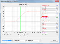
Just found this too. LTD02 shows how to do the 16 hz hpf thing with the Inuke software but he's using a shelf filter instead of the parametric eq boost that I showed in my example.
This shelf filter can also boost the entire passband, as he shows, if your signal is low. Depending on how low the signal is and how much you can boost in the Inuke software it could conceivably eliminate the need for the DI box. So two birds with one stone (signal boost and high pass filter).
Unfortunately I don't think we can sim shelfs in Hornresp so finding the appropriate filter to protect your driver would have to be done in other software.
This method would definitely boost the signal but I'm not sure if the amp lights are connected before or after the dsp section, so not sure if the boost would be included in the signal strength lights or if the boost would be downstream of the signal lights. It would be very easy to test and find out (if you had an Inuke).
Another LTD02 Designed Sub Build - Page 5 - AVS Forum | Home Theater Discussions And Reviews
JAG,
This seems to be very similar to what I need our iNuke to do.
Thanks ever so much for posting the link.
BO
Not sure if the gain stage in the amp that the dsp controls can actually do a clean 27 db dsp boost, but the dsp software suggests it can. if so that's a whole lot of dsp boost.
The graphs only go from 20 hz to 20 khz so it's unclear what the boost would do outside of that bandwidth, but it's probably boosting the entire bandwidth we are interested in (maybe). Might have to measure to make sure the boost extends down to 16 hz.
Maybe someone with an Inuke can try this 27 db dsp boost out and report back on whether it can do it cleanly or not? Also report on whether the lights are reporting input strength, input after volume knobs, input after volume knobs and dsp, or output? There's a bunch of places those lights could be connected to and reporting on. Ideally I'd hope then are reporting signal strength right after the volume knobs and dsp, right before the power amp stage, or even right at the output after the power amp stage (which seems unlikely given the wording in the manual).
I have an NU6000DSP and use it to drive up to 4x15" sealed subs for live sound (I know, sealed box isn't ideal, I like the small size and flexibility when it comes to choosing maximum SPL and LF cutoff).
The lights illuminate according to the signal leaving the amplifier. Since the power amp section will have a fixed gain, its easy to figure out when to light up the -20dB, -10dB and -6dB lights according to the line-level signal after EQ etc. The red light is, I believe, a genuine clip/limit indicator.
I've tried EQing the subs to 20Hz, requiring around 27dB of gain. Then I used the +12dB boost available in the crossover settings when messing around with a setup the other day.
So that's +39dB of boost, and the volume controls were wide open.
Stood around 1m away from the pile of speakers, I couldn't hear any hum/rumble from the subs. The gentle hiss from the compression drivers (different amp) was very much more obvious.
HTH
Chris
JAG,
This seems to be very similar to what I need our iNuke to do.
Thanks ever so much for posting the link.
BO
Like I said (a few times now), if you post a link to tb46's original Hornresp design, I can design a high pass filter in Hornresp for you and tell you EXACTLY what settings to use in the Inuke DSP.
Ideally it can be done with a simple 2nd order highpass and a single parametric eq boost, all of which can be simulated in Hornresp. But it could get more complex, requiring more than one parametric eq boost or even shelfs. I would stay away from the shelfs unless they prove necessary. They probably won't be. There are a few ways to do this, getting the Inuke to produce a hpf that it was never designed to do. That link and the previous example I showed are two such methods.
The original example I showed (approximating the 14 hz 4th order BW hpf with a 2nd order 20 hz BW hpf and a single band of parametric eq boost at 20 hz) is the way I'd like to see it done. Just need the Hornresp inputs for the design you built so I can simulate the proper Inuke settings to protect your driver.
I have an NU6000DSP and use it to drive up to 4x15" sealed subs for live sound (I know, sealed box isn't ideal, I like the small size and flexibility when it comes to choosing maximum SPL and LF cutoff).
The lights illuminate according to the signal leaving the amplifier. Since the power amp section will have a fixed gain, its easy to figure out when to light up the -20dB, -10dB and -6dB lights according to the line-level signal after EQ etc. The red light is, I believe, a genuine clip/limit indicator.
I've tried EQing the subs to 20Hz, requiring around 27dB of gain. Then I used the +12dB boost available in the crossover settings when messing around with a setup the other day.
So that's +39dB of boost, and the volume controls were wide open.
Stood around 1m away from the pile of speakers, I couldn't hear any hum/rumble from the subs. The gentle hiss from the compression drivers (different amp) was very much more obvious.
HTH
Chris
Thanks for this, good info.
The cowboy saddled his horse and ran off in all directions.
Measure twice, cut once, as the carpenter says.
B.
Measure twice, cut once, as the carpenter says.
B.
One of the things I plan to do when I next go back to the church, is use a tape measure in our pipe chamber. Comments here have gotten me thinking about the efficacy of adding two more large boxes with appropriate woofers in them.
The two himemade cabinets I built are roughly 10 cu. ft. for the SI HT18 woofer. The box containing the two Dayton ST385-8 15" Series II Woofers is just short of 13 cu. ft. in. in internal volume.
When we removed those large wooden 16 foot Bourdon pipes, we left the windchests in which they had been mounted. Those boxes are about 40 inches wide, perhaps 8 - 10 inches high and another 8 - 10 inches deep.

This crude bird's eye view of the entryway will give you a sense of the geography. Notice the Red Rectangles on the right just above the entryway door.
I'm wondering if I could put two boxes arranged as you see in this pic?
I didn't include any measurements. But I'm wondering if boxes a nominal 24 inches wide X 14-16 inches deep X 60-70 inches high could be placed in these locations. I'll use the tape measure to get the measurements in this area.
I''d just need to make sure there is room enough between these boxes and the reed pipes located on the left. I can't go too deep. But I think I can get enough height in there to get boxes that might have from 10 to 16 cu. ft. in volume.
As JAG mentioned, the lumber costs are nominal. It would just be a question of buying the right driver(s). And they could be budgeted and bought as money becomes available. With that spare XLS1500 running from the new bump box, I'd probably get more input - so the output might be high enough to power two boxes - either the original homemade boxes, or the two proposed new ones. The iNuke could get the other pair.
OK. What say you - pro or con?
Bach On
. .
The two himemade cabinets I built are roughly 10 cu. ft. for the SI HT18 woofer. The box containing the two Dayton ST385-8 15" Series II Woofers is just short of 13 cu. ft. in. in internal volume.
When we removed those large wooden 16 foot Bourdon pipes, we left the windchests in which they had been mounted. Those boxes are about 40 inches wide, perhaps 8 - 10 inches high and another 8 - 10 inches deep.
This crude bird's eye view of the entryway will give you a sense of the geography. Notice the Red Rectangles on the right just above the entryway door.
I'm wondering if I could put two boxes arranged as you see in this pic?
I didn't include any measurements. But I'm wondering if boxes a nominal 24 inches wide X 14-16 inches deep X 60-70 inches high could be placed in these locations. I'll use the tape measure to get the measurements in this area.
I''d just need to make sure there is room enough between these boxes and the reed pipes located on the left. I can't go too deep. But I think I can get enough height in there to get boxes that might have from 10 to 16 cu. ft. in volume.
As JAG mentioned, the lumber costs are nominal. It would just be a question of buying the right driver(s). And they could be budgeted and bought as money becomes available. With that spare XLS1500 running from the new bump box, I'd probably get more input - so the output might be high enough to power two boxes - either the original homemade boxes, or the two proposed new ones. The iNuke could get the other pair.
OK. What say you - pro or con?
Bach On
. .
Last edited:
More is better. Put them where you can fit them.
But if you want a recommendation I wouldn't even consider buying anything else until you have a couple of other things done.
1. Figure out and fix the power situation. Adding more subs when you can't fully power the ones you have doesn't make much sense, especially if you are not yet fully sure you will be able to fix the power problem. It might be expensive and there might be problems with adding another circuit.
2. Get some measurements of what you currently have. Frequency response measurements at different points in the audience will help a lot. You mentioned that some of the bass notes are already overpowering, I'm guessing that would be the notes well above 20 hz. I'm guessing you could use lots more UNDER 20 hz. But the subjective assessment of note strength in the sub room or at the organ position is irrelevant, you need some measurements from various places around the audience seating. if you think you can subjectively judge the strength of 16 hz by ear you are fooling yourself. You need to measure.
Once you figure out what you have (measurements) and what you can reasonably achieve (with the power situation) then you will be in a much better situation to assess what you would like to have next.
There are things you haven't dealt with yet, like for example the fact that when you get the subs fully powered they might create rattles all over the place that you can't fix. This could be a deal breaker as it can be very annoying, so there's no point in adding more until you figure out if the building can handle what you already have (once fully powered).
Step by step, take it slow, and try to work on the things (like measurements, the high pass filter settings, the Hornresp inputs for the sub you built, etc) that people have been requesting before adding piles more stuff to the system.
If you don't have a measurement mic you can get one free or borrow one. They come with most mid/high end HT receivers and should be good enough quality for this. Don't even worry about a preamp if you don't have one, just plug it right into the mic jack. Measure with REW with a sweep, not organ notes. Measure several times while moving the mic around the audience seating. This is going to be tough, you will either need REALLY long wires or two laptops to do these measurements. But in the end, if you want a good balanced system you need to do it. You can't just guess and you can't measure by ear.
Last edited:
Doubling drivers and amp power will give at most 6 dB.With that spare XLS1500 running from the new bump box, I'd probably get more input - so the output might be high enough to power two boxes - either the original homemade boxes, or the two proposed new ones. The iNuke could get the other pair.
OK. What say you - pro or con?
Bach On
. .
At 20 Hz, a 5 dB gain in SPL (sound pressure level) sounds twice as loud.
Since you have not seen the -12 dB light illuminate, your sub system has at minimum 12dB headroom left, it will get between FOUR AND EIGHT TIMES LOUDER than it presently is.
As a reminder, at four ohms, the NU 3000 is putting out the following peak watts when the meter lights illuminate:
0dB(top red light) 880 watts
-6dB 220 watts
-12dB 55 watts
-24dB 13.75 watts
I can't think of any "pro" thing to say about adding more cabinets until you find out what your speakers can do when you use more than a fraction of the headroom you have available. It's like talking about buying a faster car when you have never shifted from first gear on the one you have owned for months.
Art
2. Get some measurements of what you currently have. Frequency response measurements at different points in the audience will help a lot. You mentioned that some of the bass notes are already overpowering, I'm guessing that would be the notes well above 20 hz. I'm guessing you could use lots more UNDER 20 hz. But the subjective assessment of note strength in the sub room or at the organ position is irrelevant, you need some measurements from various places around the audience seating. if you think you can subjectively judge the strength of 16 hz by ear you are fooling yourself. You need to measure.
On a 32 foot rank of pipes ( all twelve of them ) there are but two that are below 20 hertz.
And yes you tune them by ear.
And I agree with anthony that there must be a subjective judgment of the tone level. I think Ron has said this quite a few times. He has to balance the works.
Art pointed out that gain on the signal coming in will give you more low end output.
Overall the higher notes can be tamed by Ron again as the very bottom end of the organ gets it's groove back with the greater power output.
Bummer on the shared circuit.
That's not allowed up here. Heaters have to be on their own breaker.
The window rattler circuit is most likely a dedicated line. They don't like to share their power input. And the line being a surface mount tells you that it was an afterthought.
Simplest thing to do is check if there is even any open spaces in the electrical panel to put in another circuit. That in itself may make this a difficult proposition.
And it's good to be back. First the website goes offline and then my email up in smoke.
All is back to the regular scheduled programing.
Being the chief cook and bottle washer can be challenging at times.
As a reminder, at four ohms, the NU 3000 is putting out the following peak watts when the meter lights illuminate:
0dB(top red light) 880 watts
-6dB 220 watts
-12dB 55 watts
-24dB 13.75 watts
Art
Which impedance are you calculating for?
IIRC an NU3000 will do ~45v, around 1200w into 2ohm, or 50v, around 325w, into 8ohm.
There's a German article somewhere that's measured peak outputs to be ~1.7KW/ch into 2ohm, but that's for milli-seconds, so not really applicable here.
Chris
Chris,Which impedance are you calculating for?
As a reminder, at four ohms (the OP's nominal driver load) 😉.
On a 32 foot rank of pipes ( all twelve of them ) there are but two that are below 20 hertz.
And yes you tune them by ear.
And I agree with anthony that there must be a subjective judgment of the tone level. I think Ron has said this quite a few times. He has to balance the works.
Maybe you can do some final fine tuning by ear but not initial setup tuning.
These pipes (each of them) are supposed to have a fundamental and a whole slew of harmonics that could extend into the hundreds of hz.
If you adjust by ear it's most likely you are adjusting the level of the harmonics (which are usually louder) not the fundamental.
If the frequency response is not flat (and it's probably not, IIRC even in the sim the response is not flat to 16 hz and the sim didn't include inductance effects which will drop the relative level at 16 hz even more) the 16 hz note HARMONICS might be plenty loud, but there might not be much if any of the 16 hz FUNDAMENTAL.
This is not something you can judge or adjust by ear as the harmonics will very likely swamp the fundamental and you don't know what the sample is supposed to sound like in the first place.
This is why it's ABSOLUTELY NECESSARY to measure frequency response at several different positions in the audience with ACTUAL FREQUENCY SWEEPS, not pipe organ notes.
If you think you can get this all set up and have a nice flat response by subjective testing of sampled organ notes by ear you are completely nuts. I'm guessing the response is nowhere near flat and a ton of boost at 16 hz is going to be required, even if the HARMONICS of the 16 hz note sound loud now.
- Status
- Not open for further replies.
- Home
- Loudspeakers
- Subwoofers
- Tapped Horn Cabinet for 16 Hz. organ speaker