What do you guys think if TDA7498 vs 3116/3118?
Oh and speaking of modded TDA7297 lunch money amps, I bought one of those small SMT outfitted 7297's with the tiny black heatsink and hated it. But after removing the pot and upgrading to a nicer power capacitor it sounds really nice. Clear highs perhaps even better than bigger version due to right board layout with SMT's, bass is also very punchy. The bad pot they had in there ruined everything.
Oh and speaking of modded TDA7297 lunch money amps, I bought one of those small SMT outfitted 7297's with the tiny black heatsink and hated it. But after removing the pot and upgrading to a nicer power capacitor it sounds really nice. Clear highs perhaps even better than bigger version due to right board layout with SMT's, bass is also very punchy. The bad pot they had in there ruined everything.
Last edited:
Hi Robert1325,
What power supply are you using with the Gmarsh Wiener ?
What power supply are you using with the Gmarsh Wiener ?
I've got Gmarsh's Wiener with a stepped attenuator, no pre-amp. It is better in many ways, depth, scale, composure, smooth (a bit soft?) and more detailed. But a lightly modded tda7297 is a more involving listen with cleaner bass. Brass and strings have more body, cymbals more snap.
I like both. It's been said that the tpa3116 needs a pre to get the most out of it, I've yet to try.
While looking at 2.1 tpa3116 amps last year, none had adjustable crossovers (even if they stated so)
Is that still the case?
Is that still the case?
I have not personally tried it, but I believe this one does have a low pass frequency adjustment. The description of the far left pot translates to "bass frequency adjustment"
2 1 Digital Amplifier Board Subwoofer Amp TPA3116D2 50W 50W 100W for 12V 24V Car | eBay
2 1 Digital Amplifier Board Subwoofer Amp TPA3116D2 50W 50W 100W for 12V 24V Car | eBay
I fix the amplifier by myself. The problem is that the coils are not properly positioned. I have the scheme of Brezze Audio TPA3116d2 amp. But since I did not know where to start. First, I changed all the filters at the output with the same values, but I put original WIMA capacitors,as well as at the entrance. I put on entrance 0.1 400v but I could not find the 4.7 400v to buy, only 4,7 250v. Can someone explain why is this capacitor 400v and which values can put in place of the original.
And another thing I have HECO professional b250 / 8 speakers,range from 20Hz-25KHz and high sensitivity, 40w speakers are 8Ohm. I heard that you should adjust the components on the frequency and the resistance and adjust the amp for speakers?
And another thing I have HECO professional b250 / 8 speakers,range from 20Hz-25KHz and high sensitivity, 40w speakers are 8Ohm. I heard that you should adjust the components on the frequency and the resistance and adjust the amp for speakers?
I fix the amplifier by myself. The problem is that the coils are not properly positioned. I have the scheme of Brezze Audio TPA3116d2 amp. But since I did not know where to start. First, I changed all the filters at the output with the same values, but I put original WIMA capacitors,as well as at the entrance. I put on entrance 0.1 400v but I could not find the 4.7 400v to buy, only 4,7 250v. Can someone explain why is this capacitor 400v and which values can put in place of the original.
And another thing I have HECO professional b250 / 8 speakers,range from 20Hz-25KHz and high sensitivity, 40w speakers are 8Ohm. I heard that you should adjust the components on the frequency and the resistance and adjust the amp for speakers?
400v and 250v is just the max rated voltage. Since the tpa3116 operating voltage does not come close to that, both can be used. For 8ohm speakers, you would want 22uH inductors and 680nF capacitors for the LC filter.
400v and 250v is just the max rated voltage. Since the tpa3116 operating voltage does not come close to that, both can be used. For 8ohm speakers, you would want 22uH inductors and 680nF capacitors for the LC filter.
Can you show me the schematic where to throw the inductor?

Do you think you could change some more changes to the scheme. If you could explain to me, why change and what is the result. How should I best understood. thanks
Input transformers (again) - Jensen JT-11P-1
Several pages back I was wrangling with a hum and Edcor TTPC15K/15K input transformers on my DUG-1 dual-mono tpa3116 build. After some trial-and-error, I finally got the things quiet.
Perhaps I'm a glutton for punishment, but I just swapped those transformers out for a pair of Jensen JT-11P-1 transformers, datasheet here. Now I'm back to having a constant hiss/hum. 😱
This re-build is a bit simpler, actually, in that the volume pot has been removed. So it's RCA -> JT-11P-1 -> amp board. I also now have the power supply in the same chassis, so I have all three "grounds" readily available: safety earth, chassis ground, and signal ground. (Power supply is an 18V Sigma11, FWIW.)
After studying the datasheet for too long, I decided the terms "input" and "output" are rather vague, or at least I'm over-thinking it. The datasheet diagram shows four wires coming out of the side called "OUTPUT/SHIELD/CAN", and two wires coming out of the side called "INPUT".
The OUTPUT/SHIELD/CAN wires are yellow, orange, black and white.
The INPUT wires are red and brown.
I took "INPUT" to mean input to the transformer itself (from upstream source component). So I used the red and brown wires on the chassis RCA (specifically, red to RCA+, and brown to RCA GND).
And I took "OUTPUT" to mean output from the transformer (to the amp), so I wired white to chassis ground, yellow to amp input signal+, orange to amp input signal-, and left black open.
While the amp was on, I tried connecting the black wire to the amp's input signal GND, but that actually made the hum get louder.
I tried removing the white wire from chassis earth; it doesn't appear to make a difference either way.
I also noted that the hum got quieter when I simply touched the black wire.
That touching the black wire makes the hum get quieter made me think: what if I have this backwards? What if "OUTPUT" actually means output from the upstream source device (i.e. RCA side)? And what if "INPUT" actually means input to the amp board? That idea, combined with the fact that I had to short RCA GND to transformer CT with the Edcors to get rid of hum, makes me think maybe I should try this wiring:
Yellow = RCA+
Orange = RCA GND
Black = RCA GND
White = Chassis ground
Red = amp input signal+
Brown = amp input signal-
That's one thing I plan to try.
The other thing I plan to try is an RC network between either RCA+ and RCA GND, or between amp input signal+ and signal-. These are hinted at in both the Jensen DS, and also the Lundahl LL1540 datasheet. (Again, I'm not sure what the terms input and output actually mean.)
A related sidebar: I did read that at some point, Jensen and Cinemag were the same company. And we've seen a few tpa311x builds here where the Cinemag CMLI-15/15B input transformers were used. Given that shared history between Jensen and Cinemag, and the fact that the CMLI-15/15B datasheet looks somewhat similar to the Jensen's DS, I'm assuming the wire color designations are the same. Maybe that's too bold an assumption? But, if it's a correct assumption, then my current wiring is (mostly) consistent with rhing's wiring of the Cinemag's, see pic in post #4544 of this thread. bk856er also used the same wiring in his Cinemag implementation, see post #773 in the Wiener GB thread.
Main question, then, is: given the JT-11P-1 datasheet, how would you do the wiring between RCA and amp board?
Can you show me the schematic where to throw the inductor?
It is replacing LL1, LL2, LL3, and LL4 for inductors and LC32, LC28, LC26, and LC21 for the capacitors. There is a chance that the capacitors and even the inductors are already 22uH and 680pf. Check before replacing.
Do you think you could change some more changes to the scheme. If you could explain to me, why change and what is the result. How should I best understood. thanks
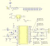
First thing to do if you want to change the stock amp is to do the "bootstrap snubber" mod which is connecting 4 sets of 330pf 50V C0G capacitor and 10ohm 5% 1/4W resistor as shown in the attachment.
The other is to replace the big electrolytic round capacitors with something with low ESR such as Panasonic's SEPF series capacitors or the like.
These two changes will improve sound quality.
Attachments
Last edited:
Jesen JT-11P-1 w/DUG-1 continued...
I was overlooking some useful documentation on the Jensen website. Their Schematics page and Applicatin Notes page have lots of useful documents.
...
Perhaps I'm a glutton for punishment, but I just swapped those transformers out for a pair of Jensen JT-11P-1 transformers, datasheet here. Now I'm back to having a constant hiss/hum. 😱
...
I was overlooking some useful documentation on the Jensen website. Their Schematics page and Applicatin Notes page have lots of useful documents.
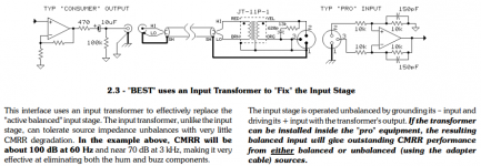
- Jensen AN-003: INTERCONNECTION OF BALANCED AND UNBALANCED EQUIPMENT, by Bill Whitlock. The bottom of Page 2, diagram 2.3 is attached below, and (I think) shows the JT-11P-1 in exactly the application in which I want to use it.
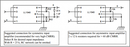
- The second pic below is the "Suggested Connection" for the Lundahl LL1540 transformers. Included just for reference, as I think they are very similar to the Jensens I'm trying to use.
- Jensen AS089: JT-11P-1 Balanced XLR Input to Unbalanced RCA Output - attached below.
- Jensen AS002: JT-11P-1 Conversion of Unbalanced Input to Balanced - attached below.
Attachments
I found this discussion here on diyAudio, talking more generally about the same application (using transformers for unbalanced to balanced conversion).
One person in that thread suggested the implementation in AS-003, as I alluded to above.
But also suggested was AS060, attached below.
With the Edcors, I was frustrated with a lack of documentation. With the Jensens, I have the opposite problem: too much information! Usually too much info is better than too little, but I lack the knowledge to actually know which docs are relevant here! 😕
Attachments
Hi Matt,
I'd try this:
Red = RCA+
Brown = RCA GND
Black = chassis ground
White = chassis ground
Yellow = amp input signal+
Orange = amp input signal-
I wonder if your issue has been that the amp chassis has been connected to the transformer case through physical contact, and/or that connecting the black wire to signal ground has coupled noise into the signal path.
Try this and let me know how it goes.
And you tried and like both equally?
Are you asking me? And about the Edcor vs the Jensen? Or the various Jensen implementations I posted? Or???
At any rate, assuming you're asking me about Edcor vs Jensen: until the hum/hiss is eliminated, I can't really say anything about the Jensens. Though when the music is loud enough to drown out the noise, they do sound good (but that was only a brief test listen). However, even when I have all this sorted out, it won't be a fair apples-to-apples comparison, as: (1) I changed the power supply when I re-built this, and (2) I removed the attenuator sitting between the RCAs and the transformers. So, I'll probably never be able to offer any kind of meaningful comparison of the transformers.
Having said that, at this point Jensen gets my vote only because they have a lot more useful documentation readily available.
Red = RCA+
Brown = RCA GND
Black = chassis ground
White = chassis ground
Yellow = amp input signal+
Orange = amp input signal-
Try this and let me know how it goes.
Hi Sharpi31, thanks for the input! I thought I'd try exactly that next, as it doesn't require me to re-solder anything, so it's quick and easy. 🙂
Also, it's a natural path to implementing the schematic in AS060 I posted above, which is exactly what you say, plus 4k99 resistors on each amp input to chassis ground. (Meaning, also really easy to test!)
I wonder if your issue has been that the amp chassis has been connected to the transformer case through physical contact, and/or that connecting the black wire to signal ground has coupled noise into the signal path.
Good idea, something to check. Though I think it "shouldn't" be the case: the transformer (Antek AS-1220) is wrapped in non-conductive material, and rests on a rubber spacer. The amp boards are mounted on nylon standoffs. Still, wouldn't be the first time I fell victim to a major oversight.
Hopefully you'll be noise and hum free very soon 🙂
Why are you wanting to add the 4K99 resistors from each amp input to chassis ground? You can certainly add resistors from the amp inputs to signal ground to reduce the amplifier input impedance to the optimal level for the transformer (the datasheet suggests 10Kohm), but bear in mind that lowering the amp input impedance may cause issues with your passive volume control. I'd be tempted not to lower the amp input impedance with additional resistors, and instead add the damping network specified in the data sheet for loads >10Kohm.
I still worry that the passive pot before the transformers may cause issues. The transformer datasheet suggests that it's designed to be driven by a low impedance source (<600ohm) but it's possible/likely that the output impedance of your passive pot can be much higher (depending on volume level). I'd use a known low impedance source instead of the passive pot while you're troubleshooting, then swap the pot back in after all is working as it should.
Good idea, something to check. Though I think it "shouldn't" be the case: the transformer (Antek AS-1220) is wrapped in non-conductive material, and rests on a rubber spacer. The amp boards are mounted on nylon standoffs. Still, wouldn't be the first time I fell victim to a major oversight.
I was meaning the audio transformers, not the power transformer 🙂
Why are you wanting to add the 4K99 resistors from each amp input to chassis ground? You can certainly add resistors from the amp inputs to signal ground to reduce the amplifier input impedance to the optimal level for the transformer (the datasheet suggests 10Kohm), but bear in mind that lowering the amp input impedance may cause issues with your passive volume control. I'd be tempted not to lower the amp input impedance with additional resistors, and instead add the damping network specified in the data sheet for loads >10Kohm.
The only reason for the 4k99 to chassis ground was because that's what they're doing in that AS060 document I mentioned above. But now that you mention it, I understand the purpose of those is just to lower impedance. So yes, I agree, those probably don't make any sense here. (If it's not obvious, I'm at a "paint by numbers" skill level here. 😉)
I still worry that the passive pot before the transformers may cause issues.
No need to worry! This is a rebuild, where I've removed the pot entirely. Volume control is now in the digital domain with my new DAC. 🙂
I was meaning the audio transformers, not the power transformer 🙂
Yeah, after I posted I wondered if I interpreted you incorrectly. 😱
At any rate, I'll try your simple suggestion shortly and report back.
Thanks again!
hi, have one tpa3116 winener modded thanks to some recommendations from great people here.. for desktop setup, any speaker recommendations that match with this amp's characteristics? diy? not diy? would not like to spend more than say $160.00 to make sense with amp.. have pioneer bs21. Thanks if you can advise!
- Home
- Amplifiers
- Class D
- TPA3116D2 Amp