Borbely tells us to aim for a total output stage bias current of at least 500mA, irrespective of the number of output devices.What would your recommendations be in terms of output stage standing current and appropriate sized heat sinks for a single pair of devices.............
This would give us a bias current of 500mA per device in a 1pair output stage.
or 250mA of bias in a 2pair output stage.
or 167mA of bias for a 3pair.
or 125mA of bias for a 4pair.
Borbely tells us to aim for a total output stage bias current of at least 500mA, irrespective of the number of output devices.
This would give us a bias current of 500mA per device in a 1pair output stage.
or 250mA of bias in a 2pair output stage.
or 167mA of bias for a 3pair.
or 125mA of bias for a 4pair.
That will give us pretty wide class A region, but a lot of dissipation.
I run most of my amps (except the ones deliberately designed for class A operation) in class AB (or B - terminology matter) - at 70-100 mA distortion is already rather low - the half-waves are stitched together well enough.
500mA of output bias gives almost 1Apk of ClassA output.
That is equivalent to just 4W of ClassA into an 8r0 test resistor.
4W is ~-14dB ref. 100W into 8r0.
Borbely, as far as I remember, did not explain why he recommended this bias, he simply stated it was for good sound.
Others have explained that mosFETs do suffer crossover distortion and the ONLY way to eliminate mosFET crossover distortion is to NOT allow crossover. That requires high bias (much higher than for BJT). Pass says something along the lines of keep increasing the (mosFET) bias until the heatsinks are as hot as you can tolerate.
Last edited:
This is best but you must wait for it. 😛Pass says something along the lines of keep increasing the (mosFET) bias until the heatsinks are as hot as you can tolerate.
500mA of output bias gives almost 1Apk of ClassA output.
That is equivalent to just 4W of ClassA into an 8r0 test resistor.
4W is ~-14dB ref. 100W into 8r0.
Borbely, as far as I remember, did not explain why he recommended this bias, he simply stated it was for good sound.
Others have explained that mosFETs do suffer crossover distortion and the ONLY way to eliminate mosFET crossover distortion is to NOT allow crossover. That requires high bias (much higher than for BJT). Pass says something along the lines of keep increasing the (mosFET) bias until the heatsinks are as hot as you can tolerate.
Unlike (single) bipolar transistor output pairs the standing current for this design can be varied without the attendant prejudices, so the amplifier can be operated in Class A into the intermediate power level range and beyond.
Some would see a full Class A build as the ultimate - others might be happy with Class AB where the point of changing mode can be anywhere in the power range.
Most listening is done at low power levels where the current for Class A coverage is less. Exactly how much would depend on the music, speaker efficiency, the room and the listener.
What this design provides is choice and flexibility. On the last score it would not be a bad idea to have a front panel control to wind back standing currents for low level listening if the normal level is into hundreds of m.a.
It well may be the wind back standing current position becomes more or less a position of permanent rest
Last edited:
It must be as follows ->
CLASS A [# ]
Volume [##### ]
CLASS B [##### ]
class must be auto linear with volume
CLASS A [### ]
Volume [### ]
CLASS B [### ]
more volume more class B
less volume more class A
CLASS A [#### ]
Volume [## ]
CLASS B [## ]
NO POWER [ * ] FULL POWER
CLASS A [ * ] CLASS B
CLASS A [# ]
Volume [##### ]
CLASS B [##### ]
class must be auto linear with volume
CLASS A [### ]
Volume [### ]
CLASS B [### ]
more volume more class B
less volume more class A
CLASS A [#### ]
Volume [## ]
CLASS B [## ]
NO POWER [ * ] FULL POWER
CLASS A [ * ] CLASS B
Last edited:
AndrewT:
Did Borbely differentiate between lateral and vertical MOSFETs with this advice?
mlloyd1
Did Borbely differentiate between lateral and vertical MOSFETs with this advice?
mlloyd1
Borbely tells us to aim for a total output stage bias current of at least 500mA, irrespective of the number of output devices.
It must be as follows ->
CLASS A [# ]
Volume [##### ]
CLASS B [##### ]
class must be auto linear with volume
CLASS A [### ]
Volume [### ]
CLASS B [### ]
more volume more class B
less volume more class A
CLASS A [#### ]
Volume [## ]
CLASS B [## ]
NO POWER [ * ] FULL POWER
CLASS A [ * ] CLASS B
You do go on.
AndrewT:
Did Borbely differentiate between lateral and vertical MOSFETs with this advice?
mlloyd1
I also thought about it, reading Andrew's post. From what I've seen, Borbely mostly used Laterals (Servo-50, Hafler DH-200, DH-500) - very different from the HexFET ones. They both like to run hot, but I consider Laterals being a better choice for class A.
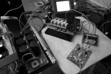
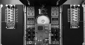
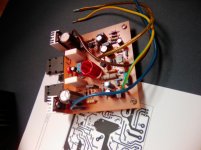
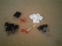
I experimented a lot with this design, before it became a finished product. Optimal quiescent current here is 80mA per pair, regardless of the number of pairs I used (IRFP240/9240 HexFETs). I tested 1, 3 and 5 pairs. More pairs = more power and higher current capability, but in any case the best results were shown at around 80mA per pair.
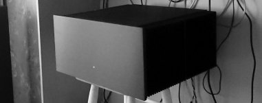
Pictures show 3 pairs on a test bench and 5 pairs in the final build.
You can see the spectrums behind the link above.
Attachments
valery:
i thought i saw the same thing that you did regarding Borbely's choice of output mosfets, hence my question.
Pass has been a big advocate of running verticals hot for his designs.
BTW, i built a servo 50 many years ago but used the low vgs toshiba verticals that are very "lateral-like" (2sk405/2sj115, LONG nla 🙁).
it's been one of my favorite amps for as many years as i've had it.
mlloyd1
Pass (mostly?) works with Vertical mosFETs and he too tells us to set the bias as high as the amplifier will tolerate.I also thought about it, reading Andrew's post. From what I've seen, Borbely mostly used Laterals (Servo-50, Hafler DH-200, DH-500) - very different from the HexFET ones. They both like to run hot, but I consider Laterals being a better choice for class A.
I experimented a lot with this design, before it became a finished product. Optimal quiescent current here is 80mA per pair, regardless of the number of pairs I used (IRFP240/9240 HexFETs). I tested 1, 3 and 5 pairs. More pairs = more power and higher current capability, but in any case the best results were shown at around 80mA per pair.
Pictures show 3 pairs on a test bench and 5 pairs in the final build.
You can see the spectrums behind the link above.
And it is not that Lateral mosFET like to run hot.
it's about bias current and avoiding crossover distortion.
We actually want our amplifier to run cold. That's why we fit heatsinks, to get the amplifier cool enough to survive what we do to them!
Pass (mostly?) works with Vertical mosFETs and he too tells us to set the bias as high as the amplifier will tolerate.
And it is not that Lateral mosFET like to run hot.
it's about bias current and avoiding crossover distortion.
We actually want our amplifier to run cold. That's why we fit heatsinks, to get the amplifier cool enough to survive what we do to them!
While you are at it why not throw germanium and silicon BJT's into the fire.
Here it is PCB lay-out, single sided. 10pf lead cap is mounted in parallel on top of R2 or under the board. I will post the PDF file for DIY etching when everything's good to go...😉
Attachments
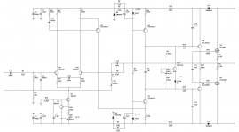
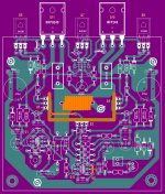
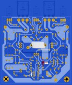
Here it is PCB lay-out, single sided. 10pf lead cap is mounted in parallel on top of R2 or under the board. I will post the PDF file for DIY etching when everything's good to go...😉
Looks very good! 😎
I also thought about it, reading Andrew's post. From what I've seen, Borbely mostly used Laterals (Servo-50, Hafler DH-200, DH-500) - very different from the HexFET ones. They both like to run hot, but I consider Laterals being a better choice for class A.
I experimented a lot with this design, before it became a finished product. Optimal quiescent current here is 80mA per pair, regardless of the number of pairs.
Interesting that Semelab do double device laterals so 8 amps becomes 16 amps n or p or a 5 lead n and p pair. An application note on their site gives their case for making these. I would not have read this except out of my interest in this thread and reading this would clear up some perceptions for non believers in your advocacy of these devices.
MosFETs don't have and "optimal" bias voltage. That applies to a ClassAB BJT output stage.
MosFETs crossover distortion becomes less as output bias is increased.
MosFETs crossover distortion becomes less as output bias is increased.
MosFETs don't have and "optimal" bias voltage. That applies to a ClassAB BJT output stage.
MosFETs crossover distortion becomes less as output bias is increased.
It's optimal in terms of the compromise between the dissipation/temperature and distortion level. As you can see from my measurements, at 80mA per pair distortion is already rather low. It doesn't make sense to run the MOSFETs hotter in order to decrease distortion further on. Distortion will go down a little bit, while the temperature will rise significantly. However, distortion is already low enough. This is true for high global loop gain designs.
- Home
- Amplifiers
- Solid State
- IRFP240/9240 Amplifier (simulated on TINA)