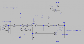
The attached schematic is the current state of the Class AB power amp infused with positive voltage feedback [PVFB]. Note the refinements:
1. PVFB and NFB emanate from the same universal power output Vo. Other power amps with topologies that are different from this amp are likely amenable to this treatment with successful results.
2. The extent of PVFB is 92% the value of NFB as calculated at the top left part of the schematic. The signals which are offered to the diff amp are mostly similar; and this invokes the maybe term of common mode, and its impact.
3. A 3-way loudspeaker, and a full range dipole loudspeaker sounded great and satisfying with this modified power amp.
4. The scope showed a 20 mVp-p 60Hz hum. The tweeter of the 3-way loudspeaker buzzed faintly. The origin of this noise is unknown, and/or signaling the onset of oscillation.
I am switching gears to experiment with positive current feedback [PCFB] by using the schematics DIYer forr showed in a past post.
Attachments
Looking promising
I am following this with great interest I am modeling an old amplifier and its input your example is very similar to my amplifiers scheme when I get home from bike ride I will Implament this to my amp
Lawrence
I am following this with great interest I am modeling an old amplifier and its input your example is very similar to my amplifiers scheme when I get home from bike ride I will Implament this to my amp
Lawrence
Antoinel...did you do distortion measurements or did you just go about listening to the amp? if you have?..... what differences did you see?
I added your little circuit to my amp but changed to 33k as this is my feedback res value
Lawrence
I added your little circuit to my amp but changed to 33k as this is my feedback res value
Lawrence
Antoinel...did you do distortion measurements or did you just go about listening to the amp? if you have?..... what differences did you see?
I added your little circuit to my amp but changed to 33k as this is my feedback res value
Lawrence
Just listening tests. Sound from the 3-way loudspeaker was full, detailed from top to bottom, and its bass was tight, big and round. I came to believe that this modified amp has now attained its full performance potential. It is important to increase the extent of PVFB slowly, and learn about the reaction of your power amp. Please show schematic for visual analysis.
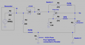
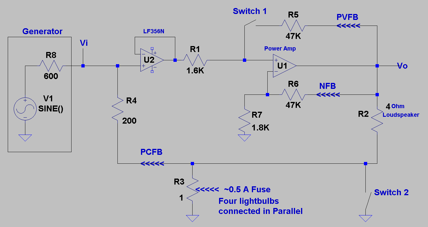
DIYer forr showed the left schematic in Post #42. It uses the standard NFB [for a closed loop voltage gain = 20], and an additional Positive Current Feedback [PCFB]. It worked with the power amp under test [Vgain = 27] as expected. A side effect of PCFB in my application was a decrease in the output voltage of the parent. This loss which is/maybe trivial can be readily restored by increasing Vi from the driving preamp, or by the application of additional Positive Voltage Feedback [PVFB] to the non-inverting port of this power amp like I described in previous posts.
The right schematic shows an approach for the application of PCFB. Please note the following:
1. The 1 Ohm resistor which senses the current flowing through the loudspeaker is a fuse made from four [Xmas] tiny light bulbs [LB] connected in parallel. I thought this special fuse will be more interesting to use than a plain resistor or a regular fuse. Because its 1 Ohm cold resistance will increase [due to heating] with current passing through it, and thus increases the extent of PCFB.
2. Closed Switch 2 across the LB fuse [no PCFB]. and generated a power output voltage of Vo [1 KHz] which I viewed on the scope and measured with a an AC multimeter.
3. Opened Switch 2 across the LB fuse [injected PCFB]. The parent power output voltage increased by ~0.6 dB.
4. Switch 2 allowed me to do a sequential A/B comparison when I used a CD music source instead of a signal generator. The two systems sounded different with a preference to that with PCFB.
5. With PCFB engaged [switch 2 off], I injected Positive Voltage Feedback [PVFB by closing Switch 1. The system was louder[expected from previous posts], sounded different from the other two, and was fully agreeable.
6. The 3 power amps described above were stable against oscillation.
7. The system with PCFB only was very quiet at idle using ADS L730 3-way loudspeaker. It became perceptibly noisier [expected from past posts] with the additional PVFB.
I'll do more listening to the systems with also the full range unenclosed loudspeaker, and report.
Attachments

4. Switch 2 allowed me to do a sequential A/B comparison when I used a CD music source instead of a signal generator. The two systems sounded different with a preference to that with PCFB.
Have you tried using a potentiometer to adjust the amount of PCFB from zero to maximum safe amount?
You should be able to carefully tune your amp+speaker cooperation to suit your taste and your acoustics.
This is a very interesting subject.
Thanks for doing these experiments and posting your results.
Cheers,
Johannes
Just listening tests. Sound from the 3-way loudspeaker was full, detailed from top to bottom, and its bass was tight, big and round. I came to believe that this modified amp has now attained its full performance potential. It is important to increase the extent of PVFB slowly, and learn about the reaction of your power amp. Please show schematic for visual analysis.
Attachments
Thank you Circlomanen for your reply, and encouragement. The purpose of my experiments is to understand the sonic value of these feedback schemes. I use existing commercial amps, and enclosed loudspeakers. They may limit the scope of cause and effect.Have you tried using a potentiometer to adjust the amount of PCFB from zero to maximum safe amount?
You should be able to carefully tune your amp+speaker cooperation to suit your taste and your acoustics.
This is a very interesting subject.
Thanks for doing these experiments and posting your results.
Cheers,
Johannes
I was thinking to insert a non-inverting op amp amplifier in the PCFB path to slowly vary the extent [of feedback] so as to approach or cause oscillation. I'll report.
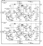
Hello Sk8Ter. Thank you for the hk schematic. It appears amenable to experimentation with PVFB; like you had mentioned in an earlier post. I'll put together a simplified schematic of it [with PVFB] for a safe starting point.
Hello Sk8Ter. The hk 430 is 1976 vintage. It delivers 25 wpc/8 Ohms. Interestingly, it has independent bipolar PSUs [maybe +/-30V] for L and R channels. Please follow this course of action [I use] to safeguard the amp's power output stage, and the loudspeaker during tweaking/experimentation.
1. Need a variac.
2. Work with one channel only. The other is the comparative reference.
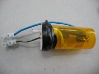
3. Construct 2 light bulb fuses. The attached photos shows one fuse which is disassembled and assembled for ready to use. Must see the light bulb and its brightness as a diagnostic, at idle and during tweaking.
4. Break the B+ power rail wire originating at the rectifier board and insert the fuse in line. Ditto for the B- power rail.
5. The amp's power output to the loudspeaker has a 3A standard fuse. Remove it and replace it with a 0.25A fuse.
6. The power output has an on/off switch to engage the loudspeakers. Keep it off.
7. No load is to be connected yet.
Powering up.
1. Plug the 2 conductor AC power cord of hk in variac.
2. Most probably, the phono circuits have an external connector labelled "phono ground". Ground/earth it.
3. Turn power switch on to hk
4. Slowly increase the variac voltage while noting the status of the light bulbs.
5. The idle current per power rail is quoted at 50 mA. Both light bulbs will slowly brighten, and level at a variac setting of 115Vac. Has idle changed after 40 years?
6. Each bulb will blow at ~120-150 mA in the event of a pre-existing malfunction or a rich bias.
7. Idle the channel under test for a time; periodically noting the light bulbs.
Turn off. Do either of the two options:
1. Turn off switch at variac set at 115 Vac; granted it has one.
2. Slowly decrease the variac voltage to zero Vac, and switch it off.
Repeat the above protocol many times to gain confidence it is reproducible before we move to the next step.
1. Need a variac.
2. Work with one channel only. The other is the comparative reference.
3. Construct 2 light bulb fuses. The attached photos shows one fuse which is disassembled and assembled for ready to use. Must see the light bulb and its brightness as a diagnostic, at idle and during tweaking.
4. Break the B+ power rail wire originating at the rectifier board and insert the fuse in line. Ditto for the B- power rail.
5. The amp's power output to the loudspeaker has a 3A standard fuse. Remove it and replace it with a 0.25A fuse.
6. The power output has an on/off switch to engage the loudspeakers. Keep it off.
7. No load is to be connected yet.
Powering up.
1. Plug the 2 conductor AC power cord of hk in variac.
2. Most probably, the phono circuits have an external connector labelled "phono ground". Ground/earth it.
3. Turn power switch on to hk
4. Slowly increase the variac voltage while noting the status of the light bulbs.
5. The idle current per power rail is quoted at 50 mA. Both light bulbs will slowly brighten, and level at a variac setting of 115Vac. Has idle changed after 40 years?
6. Each bulb will blow at ~120-150 mA in the event of a pre-existing malfunction or a rich bias.
7. Idle the channel under test for a time; periodically noting the light bulbs.
Turn off. Do either of the two options:
1. Turn off switch at variac set at 115 Vac; granted it has one.
2. Slowly decrease the variac voltage to zero Vac, and switch it off.
Repeat the above protocol many times to gain confidence it is reproducible before we move to the next step.
Attachments

I hope that the ongoing test protocol helps experimentation.So sighted listening is your only comparison? Dosnt prove much.
yes have no problem
Hello again, yes no problems I have many 430's and will experiment with one thats not that great ...so if something happens no loss LOL
anyways awaiting on the adding the pvf...
Lawrence
Hello again, yes no problems I have many 430's and will experiment with one thats not that great ...so if something happens no loss LOL
anyways awaiting on the adding the pvf...
Lawrence
So sighted listening is your only comparison? Dosnt prove much.
It proves the only thing that really matters at the end of the day: "Do you like to listen to it?"
I don't enjoy my hifi with a distortion analyzer or an oscilloscope. I like to listen to music. If I enjoy music through my amp and speakers, I am happy.
🙂
Cheers,
Johannes
So sighted listening is your only comparison? Dosnt prove much.
......... proper implementation lowers the output impedance at the cost of slightly higher distortion..........
So what do the lab results prove other than a increace in damping factor and distortion?
There are many amplifiers out there with superior specifications but also have a high listening fatigue factor.
Specifications and measurements are only 'another tool in the box', not the be all and end all.
The only thing that it proves to me is that Papa knows how to use the tools in his box.
The only thing that it proves to me is that Papa knows how to use the tools in his box.
Yes Papa is extremely crafty.
It means you can make a very simple Zen Amp, sound potentially even better. Or be able to use mosfets that might have extremely good specs but lacking transconductance to great effect by implementing positive current feedback.
On full range drivers it's probably unecessary but on regular speakers with nasty reactive loads damping factor is certainly one spec that is very audible up to a certain point.
Eg The ouput impedance of a Zen Amp may sit around 4 Ohms, reducing that to 0.1 Ohms using positive current feedback will most certainly bring about an audible difference on regular speakers (with crossovers). I think generally speaking most people would prefer that on that type of loudspeaker.
It's a great way to make a simple circuit more useful on a wider range of loudspeakers
Or be able to use mosfets that might have extremely good specs but lacking transconductance to great effect by implementing positive current feedback.
On full range drivers it's probably unecessary
Or you can have less negative voltage feedback and more total gain with a linear but not so powerful device and at the same time retain your 4 0hm output impedance. It does not have to be load invariant or even a high damping factor. The positive current feedback is a very very very useful tool to squeeze the most possible performance from a simple amp.
Cheers,
Johannes
DIYer forr showed the left schematic in Post #42. It uses the standard NFB [for a closed loop voltage gain = 20], and an additional Positive Current Feedback [PCFB]. It worked with the power amp under test [Vgain = 27] as expected. A side effect of PCFB in my application was a decrease in the output voltage of the parent. This loss which is/maybe trivial can be readily restored by increasing Vi from the driving preamp, or by the application of additional Positive Voltage Feedback [PVFB] to the non-inverting port of this power amp like I described in previous posts.
The right schematic shows an approach for the application of PCFB. Please note the following:
1. The 1 Ohm resistor which senses the current flowing through the loudspeaker is a fuse made from four [Xmas] tiny light bulbs [LB] connected in parallel. I thought this special fuse will be more interesting to use than a plain resistor or a regular fuse. Because its 1 Ohm cold resistance will increase [due to heating] with current passing through it, and thus increases the extent of PCFB.
2. Closed Switch 2 across the LB fuse [no PCFB]. and generated a power output voltage of Vo [1 KHz] which I viewed on the scope and measured with a an AC multimeter.
3. Opened Switch 2 across the LB fuse [injected PCFB]. The parent power output voltage increased by ~0.6 dB.
4. Switch 2 allowed me to do a sequential A/B comparison when I used a CD music source instead of a signal generator. The two systems sounded different with a preference to that with PCFB.
5. With PCFB engaged [switch 2 off], I injected Positive Voltage Feedback [PVFB by closing Switch 1. The system was louder[expected from previous posts], sounded different from the other two, and was fully agreeable.
6. The 3 power amps described above were stable against oscillation.
7. The system with PCFB only was very quiet at idle using ADS L730 3-way loudspeaker. It became perceptibly noisier [expected from past posts] with the additional PVFB.
I'll do more listening to the systems with also the full range unenclosed loudspeaker, and report.
Lightbulbs used as sense resistor - won't this encourage runaway feedback? I'm not so sure that would be "interesting". Depends on your definition of that, and love of the magic smoke.
I was thinking to insert a non-inverting op amp amplifier in the PCFB path to slowly vary the extent [of feedback] so as to approach or cause oscillation. I'll report.
See Figure 4 on this page:
Variable Amplifier Impedance
- Status
- Not open for further replies.
- Home
- Amplifiers
- Pass Labs
- Experimenting with Positive Feedback