Yep. He has posted another new amp in his other MOSFET thread. Thats 2 new amps in a day!.😀😀
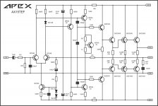
AX10, AX11TEF and FX120 is not new design, it is just modification of existing amps.
Regards
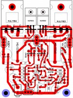
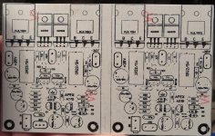
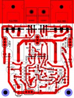
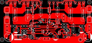
I played around with the AX10. Can one or more of you check my layout for errors before I etch a pair?
Thanks, Terry
Nice pcb, there is no errors only 100nF in parallel with LED mising.
Regards
Attachments
Last edited:
I played around with the AX10. Can one or more of you check my layout for errors before I etch a pair?
Thanks, Terry
Looks ok electrically except ofcourse as pointed by Mr. Mile.
reg
Prasi
PS: trace widths around power and o/p section needs some work. o/p appear to have unequal widths.
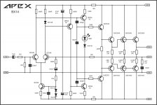
Hi Mile, can I use MJE 340-350 used instead of MPSA42-92, 2SC4793, 2SA1837 instead of MJE 340-350 and add Vbe multiplier instead of IN4148 in AX11TEF.
AX11TEF work without Vbe multiplier only 2SC5200 and 2SA1943 must be on heatsink.Hi Mile, can I use MJE 340-350 used instead of MPSA42-92, 2SC4793, 2SA1837 instead of MJE 340-350 and add Vbe multiplier instead of IN4148 in AX11TEF.
You can use MJE340/350 instead MPSA42/92 and 2SC4793/2SA1837 instead MJE340/350, I suggest to add 3 more pairs of outputs and replace BC546 with 2N5551 to get 500W amp.
Nice pcb, there is no errors only 100nF in parallel with LED mising.
Regards
The 100n is there, only slightly misplaced.
Oh, okay, so it was there added by Apex, not in original post.
Last edited:
Vbe can be use instead 4x1N4148 or LED and 1N4148 in series.
Attachments
Last edited:
Are the above 500w amps? How does the LED and diode work as opposed to transistor on AX15? I have lots of SC5200's and SA1943's.
Looks ok electrically except ofcourse as pointed by Mr. Mile.
reg
Prasi
PS: trace widths around power and o/p section needs some work. o/p appear to have unequal widths.
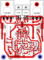
I added the cap and made some changes. I have etched a pair and will report back after I have had time to populate and test.
Attachments
Are the above 500w amps? How does the LED and diode work as opposed to transistor on AX15? I have lots of SC5200's and SA1943's.
BX20 600W/2R
Attachments
I added the cap and made some changes. I have etched a pair and will report back after I have had time to populate and test.
Nice pcb
Nice pcb
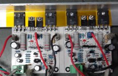
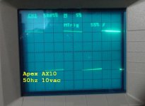
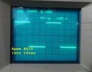
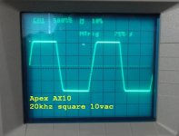
Here is is singing.
Sounds really good. I was surprised. I see 48mA on the rails and virtually 1mV across the emitter resistors yet I don't see or hear any crossover distortion. Runs fairly cool.
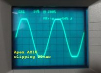
I also don't see any overshoot like on the FX8. Strange since they have the same front end. Clips right at 20vac / 8R so about 50W. Nice little amp.
Blessings, Terry
EDIT: I should point out that I installed SMD caps on the bottom side for most of the ceramic and film caps
Attachments
Last edited:
Here is is singing.
Sounds really good. I was surprised. I see 48mA on the rails and virtually 1mV across the emitter resistors yet I don't see or hear any crossover distortion. Runs fairly cool.
I also don't see any overshoot like on the FX8. Strange since they have the same front end. Clips right at 20vac / 8R so about 50W. Nice little amp.
Blessings, Terry
EDIT: I should point out that I installed SMD caps on the bottom side for most of the ceramic and film caps
Nice work, idle current go thru drivers not thru outputs... measure voltage on drivers emitter resistors (10R)
Regards
Here is is singing.
Sounds really good. I was surprised. I see 48mA on the rails and virtually 1mV across the emitter resistors yet I don't see or hear any crossover distortion. Runs fairly cool.
I also don't see any overshoot like on the FX8. Strange since they have the same front end. Clips right at 20vac / 8R so about 50W. Nice little amp.
Blessings, Terry
EDIT: I should point out that I installed SMD caps on the bottom side for most of the ceramic and film caps
Terry , You are the master of DIY
best regards
Here is is singing.
Sounds really good. I was surprised. I see 48mA on the rails and virtually 1mV across the emitter resistors yet I don't see or hear any crossover distortion. Runs fairly cool.
I also don't see any overshoot like on the FX8. Strange since they have the same front end. Clips right at 20vac / 8R so about 50W. Nice little amp.
Blessings, Terry
EDIT: I should point out that I installed SMD caps on the bottom side for most of the ceramic and film caps
This looks really clean. You must have drawer fulls of all the resistors, transistors, and caps at your disposal to build this quickly. Nice to have your own Mouser in your desk. 🙂
This looks really clean. You must have drawer fulls of all the resistors, transistors, and caps at your disposal to build this quickly. Nice to have your own Mouser in your desk. 🙂
Terry is the man when it comes to quick builds.
I usually have to wait to receive 3 boards from OSH Park along with some of the parts from Mouser.😱
Maybe I should get at least 10 values of each resistor from Tayda for pennies on the dollar.🙂
- Home
- Amplifiers
- Solid State
- 100W Ultimate Fidelity Amplifier
