AndrewT, only some of the speaker current returns to the PSU, some of it comes from the decoupling caps. I think that the feedback loop is the main problem with top layout.
I agree with your comment about the Zobel. You would need to optimize the amp board layout by placing the decoupling, Zobel and power returns close to the output return.
I agree with your comment about the Zobel. You would need to optimize the amp board layout by placing the decoupling, Zobel and power returns close to the output return.
Ultimately ALL the speaker current comes from the PSU.
That speaker current must return to the PSU.
It's the route that one allows that speaker return current to follow that is important to reducing the interference effects.
In my mind I consider speaker currents to be at low frequencies, whereas I see Zobel currents as occurring at high frequencies.
In the short term I think that difference in part determines where those two different frequencies source their current from.
The Zobel get it's current from the HF & MF decoupling and needs to return to that source. the PSU then recharges the shortbterm storage of the local decoupling.
The speaker gets it's current from the PSU with a tiny proportion from the MF decoupling and needs to return it's current to the PSU along the route of the FLOW. And that FLOW must pass through, or near the local decoupling. The speaker return current needs to pass near the local decoupling and needs to couple into the amplifier's ZERO VOLTS line close to the amplifier.
Last edited:
I have made a 6 channel power amplifier. I used 3 toroidal transformers each for 2 channels. Each channel have a separate rectifier and capacitors. From each power supply board i have only one ground wire to the chassis via a rectifier, capacitor and resistor (ground lift) to one chassis point. Of course the main ground goes directly to this chassis point and the speakers ground directly to this chassis point. With this connection there is no hum or ground loops.
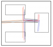
each PAIR of wires that passes a flow and returncurrent must be a close coupled PAIR.Another thing (in case of using the same PS) is the GND loop between to 2 channels as attached.
I think the 2nd version is the better. And maybe the input RCA wires should follow this main wiring as well.
Your right hand diagram gets closer to achieving that.
But is mixing a low level signal PAIR along side a HIGH current PAIR a good idea for minimising interference?
Good.I have made a 6 channel power amplifier. I used 3 toroidal transformers each for 2 channels. Each channel have a separate rectifier and capacitors. From each power supply board i have only one ground wire to the chassis via a rectifier, capacitor and resistor (ground lift) to one chassis point. Of course the main ground goes directly to this chassis point and the speakers ground directly to this chassis point. With this connection there is no hum or ground loops.
Measure your output Noise+Hum and report your "no hum" measurements.
I guess exactly that's the reason for having separate PS for each channel.But is mixing a low level signal PAIR along side a HIGH current PAIR a good idea for minimising interference?
Otherwise you have to increase your GND loop when you separate
your signal wires from PS/Speaker wires... 🙄
Hello, i have made a mistake. The speakers grounds goes to their power supply ground points and not to the chassis ground point.
When i am saying there is no hum or noise i mean audible. You cant hear absolutelly anything when you put your ear close to the speakers.
When i am saying there is no hum or noise i mean audible. You cant hear absolutelly anything when you put your ear close to the speakers.
AndrewT, perhaps the current supply is not the most important here. It is about creating a single reverence point (per channel) for the feedback loop and speaker return. The feedback loop now consists of three resistors and you want to minimize any charging or Zobel currents between speaker return and feedback return. This is the problem with the layout in post #17
Last edited:
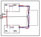
Is this version correct?
Yes - that is the correct version.
I have lost my original PPT files (probably in the move from China back to Europe) and only have the 'incorrect' HBR version in PDF. I will have to see if I can doctor it and repost it on my website.
Last edited:
I guess exactly that's the reason for having separate PS for each channel.
Otherwise you have to increase your GND loop when you separate
your signal wires from PS/Speaker wires... 🙄
That's a very expensive solution - and I don't know that it will give you any benefit.
For each channel, you run a twisted bundle of +, -, decouple ground, speaker return and if you can do it conveniently the speaker wire (i.e. you loop it back with the bundle to the PSU and then out to the output socket). If all these are bundled together, the loop areas are minimized. For the input, you go from the RCA straight to the amplifier module PCB with the HBR resistor (that's the 15 Ohm I refer to in my write up) providing the earth loop 'break' function.
Of course, if you are doing everything on a PCB, you have an opportunity to really control the layout and routing very thoroughly.
Last edited:
The Zobel can be return to the decouple ground on the amplifier boards if your decouple ground connection back to the main PSU ground is short and thick (low R and low L). If not, you can end up injecting HF noise into the decouple ground. If you are bothered about it, just check it out. I have chosen to run a separate Zobel return back to the PSU central ground, and on the nx amp PSU +Prot, I put the Zobel on the PSU board.
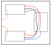
And what about a layout like this?
- input RCAs close together on the chassis
- PS wires can create a "loop"
- signal GND goes directly to main GND
- signal GNDs arent connected to local PS GND on the amp PCB at all
You have a big loop area around the input , amplifier board, power supply and back to the input. Any flux from the power transformer intersecting this loop will probably generate hum.
Personally, I would run the signal returns to the amplifier board along with the signal and not directly to the PSU as you have shown.
I would bond to the chassis from the central star ground, being careful to 'T' off to avoid charging currents. The incoming mains earth would also bond to the chassis at this point.
No and confirmed by MarkW and Bonzai.And what about a layout like this?
- input RCAs close together on the chassis
- PS wires can create a "loop"
- signal GND goes directly to main GND
- signal GNDs arent connected to local PS GND on the amp PCB at all
The input pair must run as a pair for the whole route from RCA to Amplifier.
The extra wire from Input RCA barrels to Zero volts creates a pair of LOOPS.
Those loops will inject interference.
The Source chassis must be connected to PEWhat happens when the source and the power amp are both connected to PE?
The Receiver chassis must be connected to PE.
The only exception is a double insulated, ClassII product that does not require and should not have any PE.
Now connect all exposed metal, or conductive, parts to the protected chassis.
There is a big loop around the power sockets and the connected Source and Receiver.
Any interference field impinging on that big loop will generate an interference current around the loop.
Our job is to identify where the interference current flows and identify what parts of the loop will generate an interference voltage on a part of the audio circuit. We can't break the loop!
We can attenuate the interference current and that attenuated current will result in an attenuated interference voltage on the signal circuit portion, if we insert the added resistance in the correct location.
For this PE created loop that correct position is the Disconnecting Network between the chassis and Main Audio Ground. This is the power bridge rectifier with a paralleled resistor and capacitor and maybe a switch to allow a direct wired option.
IMO the PE should never be directly connected to any GND in any system.What happens when the source and the power amp are both connected to PE?
It's just a safety potential for metal cases but nothing else...
I don't see any loop there, that's the point. That's why I said "loop" as well.You have a big loop area around the input , amplifier board, power supply and
back to the input. Any flux from the power transformer intersecting this loop will probably generate hum.
It's looks like but there isn't. (The signal GND is not connected with the PS GND on the PCB!)
So (if you would like) you can bring the PS wires whereever you like.
I am not sure what you are saying (maybe a quick paint work to explain..?) but if thePersonally, I would run the signal returns to the amplifier
board along with the signal and not directly to the PSU as you have shown.
signal GND is not going via 1 wire only to main GND, then will be a loop created.
It's exactly like this: there goes 1 pair of wires from RCA to the amp.The input pair must run as a pair for the whole route from RCA to Amplifier.
I am not sure how much noise it would create with wires close to eachother.The extra wire from Input RCA barrels to Zero volts creates a pair of LOOPS.
Those loops will inject interference.
Or it can be implemented without loop as well: taking the signal GNDs
from that wire going to the amp PCBs exactly as my image shows.
An other thing: I am not sure but maybe with this layout a 10R resistor can
be applied in series with this wire..?! (These 2 potentials should not change a lot so
the main goal there is basically just the "equalization" of this 2 potentials, right?)
From your drawing, it looks like you have connected the RCA 0V to both the amplifier boards and the PSU star ground. That will create an earth loop.
- Status
- Not open for further replies.
- Home
- Amplifiers
- Solid State
- 6-channel-amplifier-grounding