Hi Cortez,
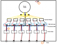
Thanks for the reply. I think your second suggestion was this? This is easier to implement and there look to be up to 15 or more loops in that design? 😕
Also is there a need to common all of the capacitor sets together into one long block? If two channels were plugged into the same source with a common line level ground then this would create a loop? It will be difficult practically to implement this (see cad drawing in my first post to see why).
Of course a chassis PE will be mandatory, Andrew T you can be assured of this!
Thanks
Attachments
Last edited:
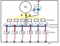
And the Bonsai version if I am correct:
- no common RCA GND
- (tightly twisted) signal wires are going directly to amp PCB
- on amp PCB signal GND goes via a 15R to the PS GND
- PE goes directly to the chassis
- PE goes via a 15R + rectifier combo to common PS GND
- optional: 1nF from every RCA GND to chassis with short legs
Attachments
Well, I would connect them together as shown.Also is there a need to common all of the capacitor sets together into one long block? If two channels were plugged into the same source with a common line level ground then this would create a loop?
I am not sure about a layout with "floating" PS GND for every channel... 🙄
Anyways if they should be tied together I would do it rather "behind" the caps,
so on the rectifiers side to exclude any current taken from the amplifier side...
But let's wait for the real experts to be sure... 😉
Last edited:
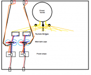
Do we need all 6 channels on the same drawing ?
If we could do it just for two it would save some space. And help to build the understanding.
Than once we have a clear understanding for a stereo set, we can draw a full 6 channels diagram.
What do you think
If we could do it just for two it would save some space. And help to build the understanding.
Than once we have a clear understanding for a stereo set, we can draw a full 6 channels diagram.
What do you think
Cortez, your last layout looks good to me. You could move the common ground to the other side of the caps with each amp connected to its own pair of capacitors.
Use 1 Ohm resistors for the amps and place them between the power and signal grounds, as in Bonsai's updated schematic.
Matt09, do you know which amps you are going to use?
Use 1 Ohm resistors for the amps and place them between the power and signal grounds, as in Bonsai's updated schematic.
Matt09, do you know which amps you are going to use?
I agree.Do we need all 6 channels on the same drawing ?
If we could do it just for two it would save some space. And help to build the understanding.
Than once we have a clear understanding for a stereo set, we can draw a full 6 channels diagram.
What do you think
Draw a mono set up and understand why it works and where the wires need to run to allow it to work.
Then extend that to include TWO channels. Add in any modification to get two channels to work.
The major learning experience with the mono set up is that ALL signal pairs/triplets must be kept as close coupled wires/traces to minimise interference.
That learned technique MUST be carried over to the two channel version.
And one final point.
Using a centre tapped secondary requires ALL the channels to share a common Voltage Reference
Last edited:
Like this..?
After thinking of Matt's idea without a common PS GND between channels I am
not sure about it being wrong... Why it would be a problem to create a separate
floating PS GNDs for each amp just with using the common point of the filter caps?
What does it help just to connect this point to a "wire" from the trafo..?
Or why to bring it together with the other channels PS GND?
Attachments
You need to add in the Transformer Centre Tap to run alongside the two AC wires towards the bridge rectifier. This is the first twisted triplet.
From the bridge rectifier, the CT and the two AC wires remain close coupled (or preferably the next twisted triplet) till they reach the smoothing capacitors.
From the smoothing capacitors continue the twisted triplet to the amplifier PCB. Cortez shows this triplet in post67.
From the PCB power input pads the three power traces should remain close coupled to the main current consumers.
That adds up to four sets of triplets from transformer to Output devices. The mono build has to get this right.
Then repeat for the two channel build. EACH channel in the two channel build will have 4 sets of triplets from transformer to output devices.
Some PCB layout designers will use three separate power planes to achieve the close coupling of the +ve, zero volts and -ve on the PCB. This is perfectly acceptable, but cannot be replicated with a 2layer PCB.
It needs at least 4layers, one needs a signal plane and a signal ground plane in addition to the three power planes to create the three adjacent power planes and according to H.Ott one needs at least 6layers to do it properly,
Last edited:
I don't get this 4 sets of triple / channel thing.That adds up to four sets of triplets from transformer to Output devices.
Isn't it enough just to use the 3 wires from PS to amp?
three wires from PSU to mono amplifier is a twisted triplet.
Your diagram splits this route into three parts. The fourth part is on the amplifier PCB.
You NEED all three power wires to feed power into the amplifier.
You need to repeat this three wire power supply for EACH amplifier.
Read post68 again. You seem to have missed something in there.
Your diagram splits this route into three parts. The fourth part is on the amplifier PCB.
You NEED all three power wires to feed power into the amplifier.
You need to repeat this three wire power supply for EACH amplifier.
Read post68 again. You seem to have missed something in there.
Ok I understand now they are in series so 1 triplet with 4 sections:
trafo - (1st) - rectifier - (2nd) - caps - (3rd) - amp OPS - (4th) - amp IPS, right?
Still an open question: what happens if for channel level PS GND we use the common
GNDs between main filter caps but without connecting it to the trafos center tap?
trafo - (1st) - rectifier - (2nd) - caps - (3rd) - amp OPS - (4th) - amp IPS, right?
Still an open question: what happens if for channel level PS GND we use the common
GNDs between main filter caps but without connecting it to the trafos center tap?
That would break the close coupled rule and introduce avoidable interference.what happens if for channel level PS GND we use the common
GNDs between main filter caps but without connecting it to the trafos center tap?
Everyone must use the Centre Tap. It is the PSU zero volts and that must be connected to every amplifier
I said in post66
Start simple and get the simple working properly.Draw a mono set up and understand why it works and where the wires need to run to allow it to work.
I also said in post66
The major learning experience with the mono set up is that ALL signal pairs/triplets must be kept as close coupled wires/traces to minimise interference.
Last edited:
OK. You have one PSU so one PSU ground so one signal ground for the six channels. This is the opposite of monoblocks! It is almost impossible to avoid ground-related buzz in such a setup.matt09 said:I have one very large power transformer with one + and - winding.
This feeds six separate Thyristor bridge's (so I can turn each channel off to save power)
I have 6 sets of capacitors from each Thyristor bridge.
The above is fixed, I have acquired these parts and don't intend on changing transformers or capacitors now.
You should try to include a connection from signal ground to the chassis, but it is unclear to me exactly where this should be. You can't do it at an input, as you have six inputs. You can't do it at a clean PSU output, as you have six clean PSU outputs. I guess you will have to do it at the only common point you have which is the PSU ground; this may be dirty so could give hum.Do I connect the cap common points to the PE ground at all?
My advice is to start again, but I know you have reasons for not taking this advice. You need one PSU driving six amp channels, or six separate PSUs (i.e. six separate pairs of secondaries) driving one channel each. Your hybrid is about the worst possible way to do it. Trying to add magnetic shielding around the transformer will not help as it misses the point.
But what if we forget that center tap for a while and create just aThat would break the close coupled rule and introduce avoidable interference.
Everyone must use the Centre Tap. It is the PSU zero volts and that must be connected to every amplifier
"floating" PS GND between the caps independently for all 6 channels?
And in this case even the signal GND could or rather should to connect to this point directly (without R).
Why would it be wrong?
Last edited:
One cannot just discard the Centre Tap.
He has a centre tapped transformer and that MUST be connected to the Zero Volts of the dual polarity power supply.
There is no choice in that.
Draw out a MONO build if you want to learn anything.
He has a centre tapped transformer and that MUST be connected to the Zero Volts of the dual polarity power supply.
There is no choice in that.
Draw out a MONO build if you want to learn anything.
I guess there would be nothing wrong not using the center tap at all...
And then the all signal GNDs could/should go directly to these "floating" PS GNDs in the middle of the PS caps.
But please say (or rather show an evidence) if this layout has anything wrong because I don't see any...
On the contrary: this might be the best solution regarding Matt's given circumstances.
Last edited:
I must have misunderstood what you mean. The secondary centre tap must be connected to the zero volts line where the reservoir caps all meet. If not, you don't have a bipolar PSU but a single rail PSU. You can't run a bipolar amp from a single rail PSU.Cortez said:I guess there would be nothing wrong not using the center tap at all...
Why not? The common point at the PS caps (without connecting it to the trafo center tap)
gives a GND reference point. What's wrong with using that as a normal GND point?
gives a GND reference point. What's wrong with using that as a normal GND point?
Hi All,
Thanks for the contributions.
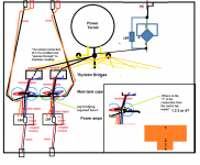
Andrew T please can you confirm if I have understood you correctly, my diagram is based on your comments.
Also please could you confirm if capacitor busbar commoning should be employed across channel sets as in the diagram? (commoning is badly off centre so all wires can be seen, but I would common properly at the centre).
I am also unsure where on each T the separate CT connections from Toroid should be made? I assume it should be as "1"..?
Lastly is this the most suitable method of connecting the CT to PE, or should it be made from the capacitor bus bar block?
Thanks
Thanks for the contributions.
Andrew T please can you confirm if I have understood you correctly, my diagram is based on your comments.
Also please could you confirm if capacitor busbar commoning should be employed across channel sets as in the diagram? (commoning is badly off centre so all wires can be seen, but I would common properly at the centre).
I am also unsure where on each T the separate CT connections from Toroid should be made? I assume it should be as "1"..?
Lastly is this the most suitable method of connecting the CT to PE, or should it be made from the capacitor bus bar block?
Thanks
Attachments
Last edited:
Matt, BTW are you far from realizing this project? At least on module level?
Because I think it would be really useful (for all of us) to try these things out in real life.
It would only take a few minutes once you are ready with your modules
and you could find out the best topology questioning the reality.
For example I still think that maybe the best solution would be what you
mentioned earlier about not using a common PS GND (and the center tap)
between the 6 channels but having a floating GND for each channel separately.
With this layout all the inputs would drive its own amp directly and beside that you
wouldn't have any GND loop in your system even when using different devices at the inputs.
- Status
- Not open for further replies.
- Home
- Amplifiers
- Solid State
- 6-channel-amplifier-grounding